Chamfer Callout Drawing
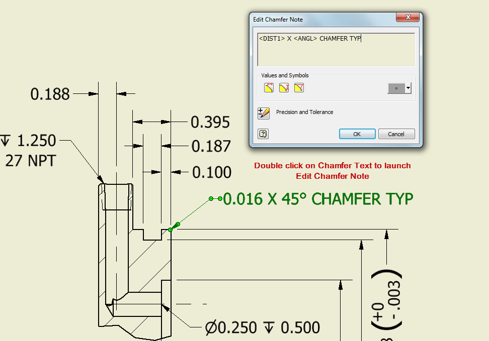
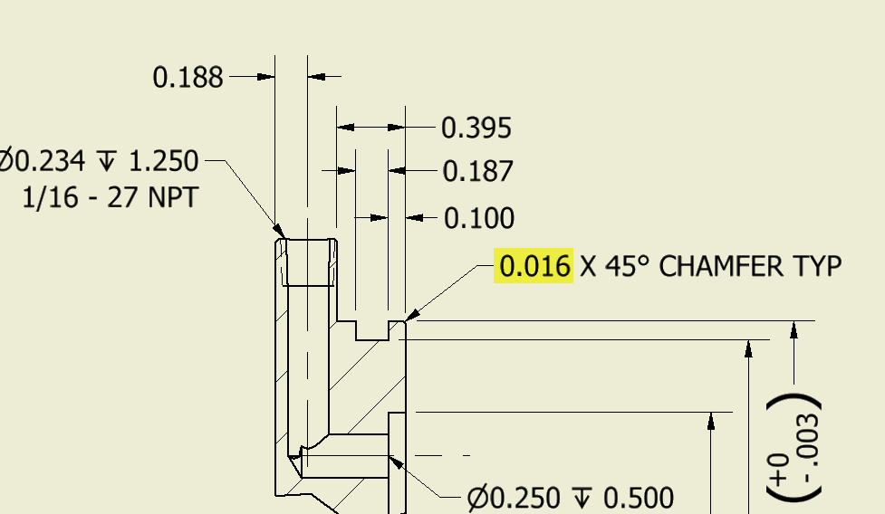
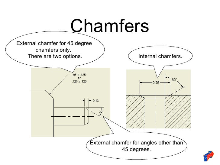
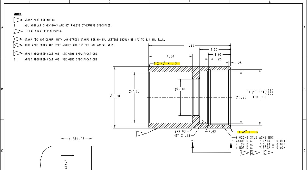
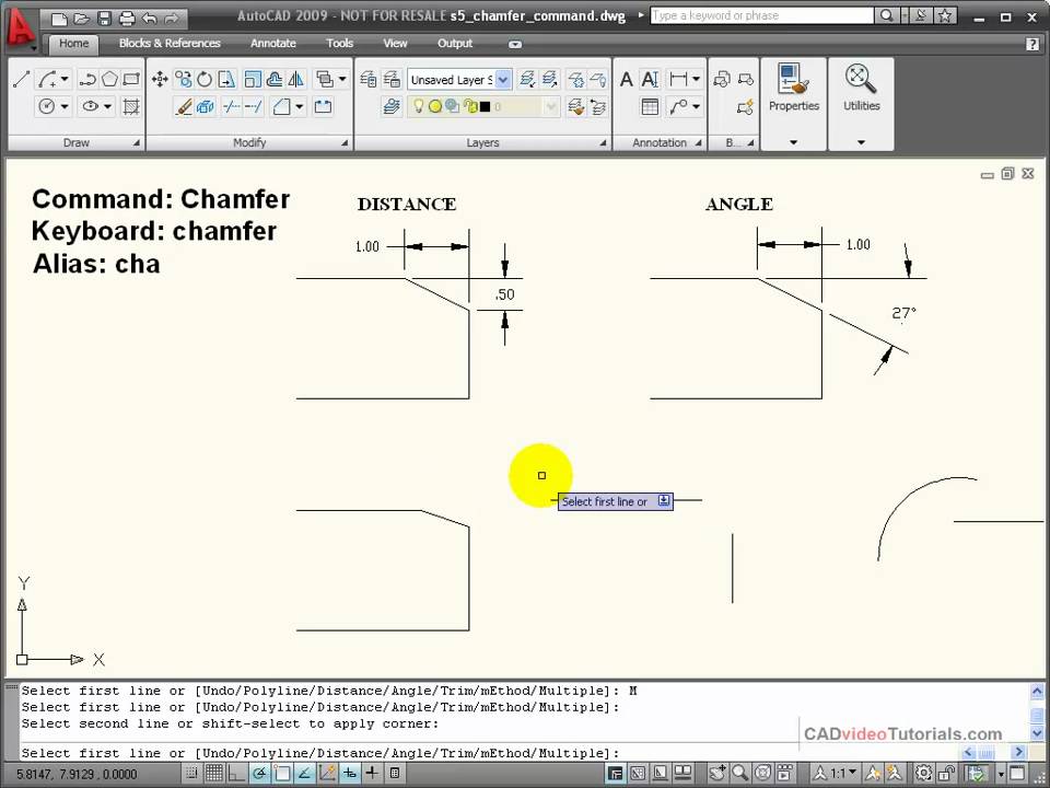
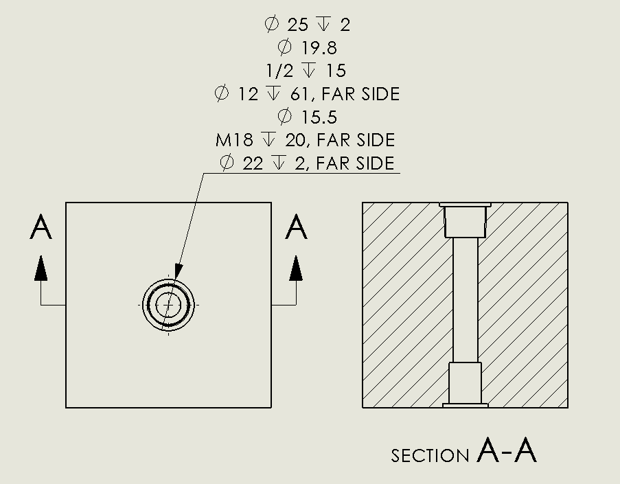
Chamfer Callout Drawing - See figure 2 for chamfer dimensioning examples. Web a convenient guide for geometric dimensioning and tolerancing (gd&t) symbols at your fingertips. If an angle other than 45 degrees is dimensioned, the surface to which the angle is measured must be made clear on the drawing. Web chamfers, rounds, fillets, and “break edges” are edge features that you may commonly see on your part drawings. Chamfers are often left as an afterthought for blueprint drafters. Y14.5 clearly says a note 1 x 1 or 1 x 45° is allowed. Designers can instruct with “break all edges” on the drawing and indicate a chamfer size, or they can add a note specifying that all sharp edges should be deburred. Web dimensioning a chamfer in a drawing: • if the chamfer was created using the chamfer feature in creo, dimensions can be shown directly in the drawing. Web the standard is intended to provide uniformity in drawing specifications and interpretation, reducing guesswork throughout the manufacturing process. In this article, you will learn the proper way to do a chamfer callout, as well as how to do the callout in popular software programs. Web the standard is intended to provide uniformity in drawing specifications and interpretation, reducing guesswork throughout the manufacturing process. Web chamfers, rounds, fillets, and “break edges” are edge features that you may commonly see. If it is not clear that a hole is a thru hole by looking at the drawing, then a depth or thru needs to be added to the callout. Click on the links below to learn more about each gd&t symbol or concept, and be sure to download the free wall chart for a quick reference when at your desk. Web what is the correct way to call out a 45 degree chamfer? Solidwork has a dimension style that is c1 for 45 degree chamfers. Is this correct or do i have it backwards? Steps creating a hole or thread callout: In addition to the usual dimension display properties, chamfer dimensions have their own options for leader display, text display,. In this article, you will learn the proper way to do a chamfer callout, as well as how to do the callout in popular software programs. If it is not clear that a hole is a thru hole by looking at the drawing, then a depth or thru needs to be added to the callout. Designers can instruct with “break. .040 x 30) to my knowledge the.040 be the depth into the material and the 30 degrees is the angle from the centerline. Y14.5 clearly says a note 1 x 1 or 1 x 45° is allowed. Web dimensioning a chamfer in a drawing: The terms “break edge” and “deburr” are similar. Web what is the standard for a callout. Standards allow for a common language to be used between you and the optician so there is no confusion regarding the features desired in the final part. But according to iso 13 715 there is also something called edge condition. In addition to the usual dimension display properties, chamfer dimensions have their own options for leader display, text display, and. Through this method, y14.5 aims to improve quality, lower costs, and shorten deliveries wherever mechanical parts are designed or manufactured. They are used for a variety of reasons, which typically include: Web what is the standard for a callout of a chamfer feature? I have been using this style for many years with multiple companies and drafting programs and have. Web using 180 grit fine sandpaper is the easiest way to create a break edge on a wooden workpiece. Many times they have no functional requirement but are merely added to protect the part and anyone who might come into contact with it. Standards allow for a common language to be used between you and the optician so there is. Chamfers can be dimensioned in two ways, either by calling out the length by angle, or calling out the length by length. I have been using this style for many years with multiple companies and drafting programs and have never questioned it. In addition to the usual dimension display properties, chamfer dimensions have their own options for leader display, text. Y14.5 clearly says a note 1 x 1 or 1 x 45° is allowed. Steps creating a hole or thread callout: Part strength, burr removal, ease of assembly, and aesthetics. Through this method, y14.5 aims to improve quality, lower costs, and shorten deliveries wherever mechanical parts are designed or manufactured. Web a convenient guide for geometric dimensioning and tolerancing (gd&t). Web you can dimension chamfers in drawings. If an angle other than 45 degrees is dimensioned, the surface to which the angle is measured must be made clear on the drawing. Select a circle that is part of a hole feature, or a thread that is part of an. Web if the chamfer is only part way around the cylinder, then more information is needed, such as where does it begin or end. Y14.5 clearly says a note 1 x 1 or 1 x 45° is allowed. See figure 2 for chamfer dimensioning examples. Web dimensioning a chamfer in a drawing: In addition to the usual dimension display properties, chamfer dimensions have their own options for leader display, text display, and x display. Web what is the correct way to call out a 45 degree chamfer? This allows to determine the shape of parts edges and corners. Both tolerance types may be used for multiple levels of control, which are described in detail in the section on profile tolerances. Chamfers are often left as an afterthought for blueprint drafters. Another way is to draw a line where you want the chamfer to be placed, then use sketch dimension to position it exactly where you want. Web what is the standard for a callout of a chamfer feature? Web a countersink is an angled taper applied to a hole that allows a fastener (usually a flat head screw or similar) to sit even with, or below the surface which has been countersunk. Web chamfers, rounds, fillets, and “break edges” are edge features that you may commonly see on your part drawings.
Adding a Chamfer Dimension YouTube
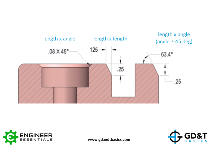
Chamfer Dimensioning GD&T Basics
Dimensioning standards
Solved Multiple chamfers on drawings PTC Community
Inventor Ability to change the decimal places in the call out of the

SolidWorks Tutorial How to Add Chamfer Dimension In Solidworks Drawing
AutoCAD Tutorial Using the CHAMFER Command YouTube
Engineering Drawing Chamfer Callout

How to Use SolidWorks Sketch Chamfer Tool Tutorial for Beginners
Inventor Ability to change the decimal places in the call out of the
Is This Correct Or Do I Have It Backwards?
Web When The Chamfer Has To Be Toleranced, Then One Has To Add The Allowed Deviation (E.g 0,3±0,2X45°).
Occasionally, A Countersink Is Used Simply As A Method Of Chamfering Or Deburring A Hole.
Optical Drawings Provide A Precise Definition Of Your Optic For Fabrication.
Related Post: