Countersink Callout Drawing
Countersink Callout Drawing - Ewh (aerospace) 15 feb 06 15:40. The units of the print are very important because there is a huge difference between 25.4mm and 25.4 inches. Web when the hole tab is open, click the note tab. The purpose of a countersink is to allow a fastener, typically a flathead screw, to sit slightly below the surface of. For ansi/imperial fasteners, it is commonly at 82°, 90° for metric fasteners, 100° for ba threaded fasteners, and 120° for. Web units of measurement. Web extracted to 2d drawings. A countersink hole is one in which the outer edge of the hole has been opened up to a conical entry. Web the gd&t callout for a countersink is shown below. An arc length is dimensioned using the arc length symbol. Web 15 feb 06 15:23. 1.1 symbols permit consistency in the way dimensions and tolerances are specified, and each symbol has a clearly defined meaning. The measurement units will often be called out in the title block or tolerance block but occasionally will be in another section of the blueprint such as in the notes. Countersink drawings play a crucial. Web you can add hole callouts in standard drawing views and in section views. 1.1 symbols permit consistency in the way dimensions and tolerances are specified, and each symbol has a clearly defined meaning. Annotation standardization is provided by the asme Countersinks allow a screwhead to sit slightly below the surface of a part to. Countersink drawings play a crucial. How to dimension a countersink. I don't have access to someone who knows and i am not a mechanical person. Jkilgore (mechanical) (op) 12 jun 07 11:50. Web in the example below, the drawing calls out five thru holes of a diameter between 0.531 and 0.546, each with a counterbore having a diameter of 0.813 to 0.828 and a depth. 3 specify the standard as ansi inch, the type as hex screw, the size as a 3/8 diameter, and the end condition as through all. C read and interpret callouts for common machining notes processes such as necks, keyways, and knurls. Click the edge of a hole, then click in the graphics area to place the hole callout. Draw the. The symbols used for each hole and how they are shown on engineering drawings. You can edit the hole note after the hole feature is created: What the difference is between counterbore and countersink holes. Calling out a countersink in a drawing requires the 3 dimensions to be called out along with the appropriate gd&t symbols. The different types of. Overwhelmed by the complexity of gd&t? Web when the hole tab is open, click the note tab. These callouts help ensure consistency and accuracy during manufacturing and assembly processes. Web key steps in calling out countersink drawings. For a symmetric part, it is only necessary to dimension to one side of the center line of symmetry. In this guide you’ll learn: This is a complete guide to the types of holes found in machining. The purpose of a countersink is to allow a fastener, typically a flathead screw, to sit slightly below the surface of. Some older blueprints may use the notation csk to identify a countersink dimension. Web an engineering drawing or design document that. I don't have access to someone who knows and i am not a mechanical person. Web a countersink consists of a conical hole that is coaxial to a cylindrical hole, where the angle of the cone is determined by the fastener to be used. Check the add a note check box to create the hole note. Click the edge of. Web extracted to 2d drawings. In this guide you’ll learn: You can edit the hole note after the hole feature is created: Check the add a note check box to create the hole note. The symbols used for each hole and how they are shown on engineering drawings. Click hole callout (annotation toolbar), or click insert > annotations > hole callout. Is this hole going into a flat surface? In the graphics window, select the note. • do not cross leader lines. Web units of measurement. The callout is as follows: See this list for other common keyboard shortcuts for gd&t and blueprint symbols. Draw the leader, or dimension line, with the arrow just touching the edge of the outer circle of the countersunk hole. Calling out a countersink in a drawing requires the 3 dimensions to be called out along with the appropriate gd&t symbols. In the graphics window, select the note. Counterbored holes are specified by giving the diameter of the drill, the diameter of the counterbore, and the depth of the counterbore. The units of the print are very important because there is a huge difference between 25.4mm and 25.4 inches. This handout will focus on the standards of annotation for fasteners, and hole callouts (local notes). A countersink hole is one in which the outer edge of the hole has been opened up to a conical entry. In the model tree, expand the hole feature, and select the note. Overwhelmed by the complexity of gd&t? Web you can add hole callouts in standard drawing views and in section views. Perform one of the following actions: How each type of hole is used in engineering. Check the add a note check box to create the hole note. Draw the line radially, so that it points toward the center of the hole, and if extended it would pass through the center point.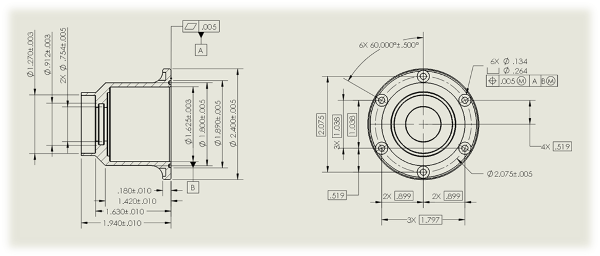
Tips and Tricks for Defining and Organizing Hole Callouts in SOLIDWORKS
Countersink Example3 OER

Types of Holes The Complete Guide The Engineer's Bible
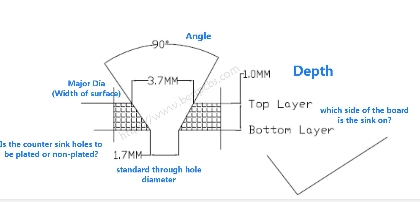
What’s the Countersink and counter bore on a PCB drawing?

PLTW IED 5.5 Countersink in Fusion 360 YouTube

PPT Chapter 10 cont. PowerPoint Presentation, free download ID1984589
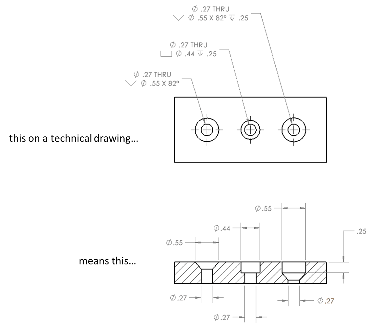
The Benefits of Countersinking SendCutSend
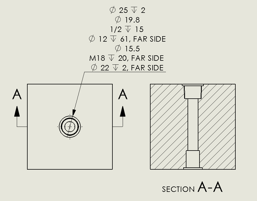
SOLIDWORKS 2018 Advanced Hole & Callout Tutorial Innova Systems
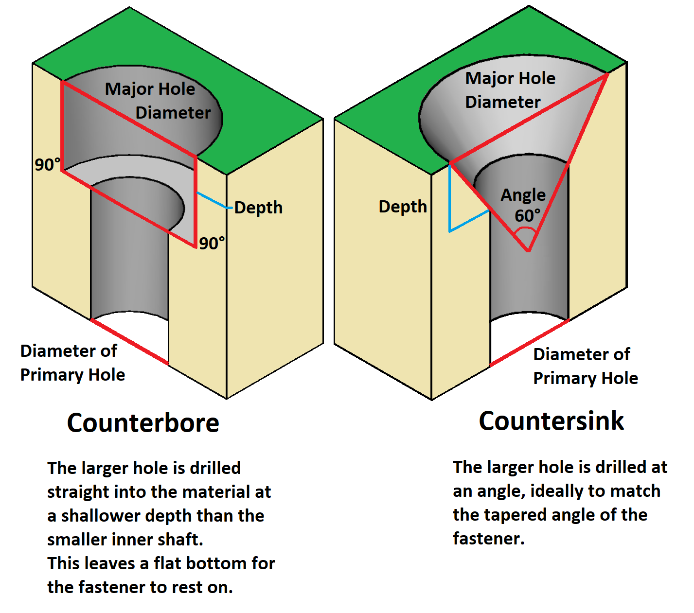
PCB Hole Types Counterbore vs Countersink ABL Circuits
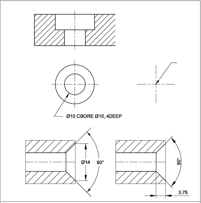
ENGINEERING DRAWING Dimensioning
For A Symmetric Part, It Is Only Necessary To Dimension To One Side Of The Center Line Of Symmetry.
Web The Gd&T Callout For A Countersink Is Shown Below.
Defining Baselines To Dimensions Typically Keeps Dimensions Clean And Organized.
Countersink Drawings Play A Crucial Role In Manufacturing And Engineering Processes.
Related Post: