Dimension Drawings
Dimension Drawings - Dimension line is a continuous thin line. Scaled 2d drawings and 3d models available for download. They provide measurements that define the length, width, height, or diameter of objects, allowing for accurate replication and manufacturing. Extension line, dimension line, nominal value, and terminator. Drawing dimensions are expressed as numeric constants. Web a comprehensive reference database of dimensioned drawings documenting the standard measurements and sizes of the everyday objects and spaces that make up our world. Click to place the dimension in the drawing. Basic dimension — a numerical value defining the theoretically exact size, location, or orientation relative to a coordinate system. Solution for task 5.6 convert the orthographic drawing shown below into an isometric drawings. It is indicated by arrowheads, it is drawn parallel to the surface whose length must be indicated. Determine the relative position and size between the basic shapes. Click a highlighted drawing entity (circle, arc, circle center, line, centermark, or point). Make a the lowest point of the drawing. Click power dimensioning > edit > edit dim text. It is indicated by arrowheads, it is drawn parallel to the surface whose length must be indicated. By the end of this chapter, you should be able to: Click a highlighted drawing entity (circle, arc, circle center, line, centermark, or point). Dimensions and notations must be placed on the sketch where they can be clearly and easily read. Scaled 2d drawings and 3d models available for download. Web in machine sketches and drawings, in which fractions and. On a multiview drawing, dimensions should generally be placed between adjacent views. Dimension line is a continuous thin line. Drawings normally only give each dimension once. Extension line, dimension line, nominal value, and terminator. Web the dimension tool for drawings work much like the dimension tool for sketches. Dimensions and notations must be placed on the sketch where they can be clearly and easily read. Web the following illustration demonstrates one method for using the dim command. Drawing dimensions are expressed as numeric constants. Web a comprehensive reference database of dimensioned drawings documenting the standard measurements and sizes of the everyday objects and spaces that make up our. Web a comprehensive reference database of dimensioned drawings documenting the standard measurements and sizes of the everyday objects and spaces that make up our world. Basic dimension — a numerical value defining the theoretically exact size, location, or orientation relative to a coordinate system. Use scale rulers to determine actual dimensions from drawings. Documenting the standard measurements and sizes of.. Documenting the standard measurements and sizes of. You can add text to a dimension. Web the following illustration demonstrates one method for using the dim command. Scaled 2d drawings and 3d models available for download. Web a comprehensive reference database of dimensioned drawings documenting the standard measurements and sizes of the everyday objects and spaces that make up our world. Web dimension — the numerical value that defines the size, shape, location, surface texture, or geometric characteristic of a feature. Task 5.6 convert the orthographic drawing shown below into an isometric drawings. Determine the size of the shape and size of each component of the assembly. Web essentially, dimensioning refers to the process of specifying the exact size, shape, and. Activate the tool (click the icon or use the d shortcut), then: Dimension lines are drawn as continuous, thin lines with arrowheads at each end. Web drawing dimensions are added to a drawing to further document the model, without changing or controlling features or part size. Web architect bryan maddock created a public research database dubbed dimensions.guide as a comprehensive. Determine the size of the shape and size of each component of the assembly. It is indicated by arrowheads, it is drawn parallel to the surface whose length must be indicated. Property indicators (symbols) rules for dimensioning. Web the process of adding size information to a drawing is known as dimensioning the drawing. In architectural and structural sketches and drawings,. In architectural and structural sketches and drawings, the numerals are usually above an unbroken dimension line. Use scale rulers to determine actual dimensions from drawings. Make a the lowest point of the drawing. Scaled 2d drawings and 3d models available for download. Determine the relative position and size between the basic shapes. Scaled 2d drawings and 3d models available for download. Scaled 2d drawings and 3d models available for download. Geometrics is the science of specifying and tolerancing the shapes and locations of features on objects. Web dimensions are drawn by locating a series of points that define the anchor point (the point from which distances are measured), direction (the axis along which distances are measured), the dimension line offset (the location of the first dimension line), and the dimension nodes (the points to which each distance is measured). Web for most of the architectural drawing best practices, the source is national cad standards (ncs, usa). Once you start the command, select the line (1), and then click the location of the dimension line (2). Solution for task 5.6 convert the orthographic drawing shown below into an isometric drawings. On a multiview drawing, dimensions should generally be placed between adjacent views. Activate the tool (click the icon or use the d shortcut), then: You start the dim command, click two endpoints (1 and 2) and then the location of the dimension line (3). Click power dimensioning > edit > edit dim text. Determine the size of the shape and size of each component of the assembly. Determine the relative position and size between the basic shapes. Basic dimension — a numerical value defining the theoretically exact size, location, or orientation relative to a coordinate system. Any measurements that you need should be somewhere on the drawings. Web in machine sketches and drawings, in which fractions and decimals are used for dimensions, the dimension line is usually broken near the middle to provide open space for the dimension numerals.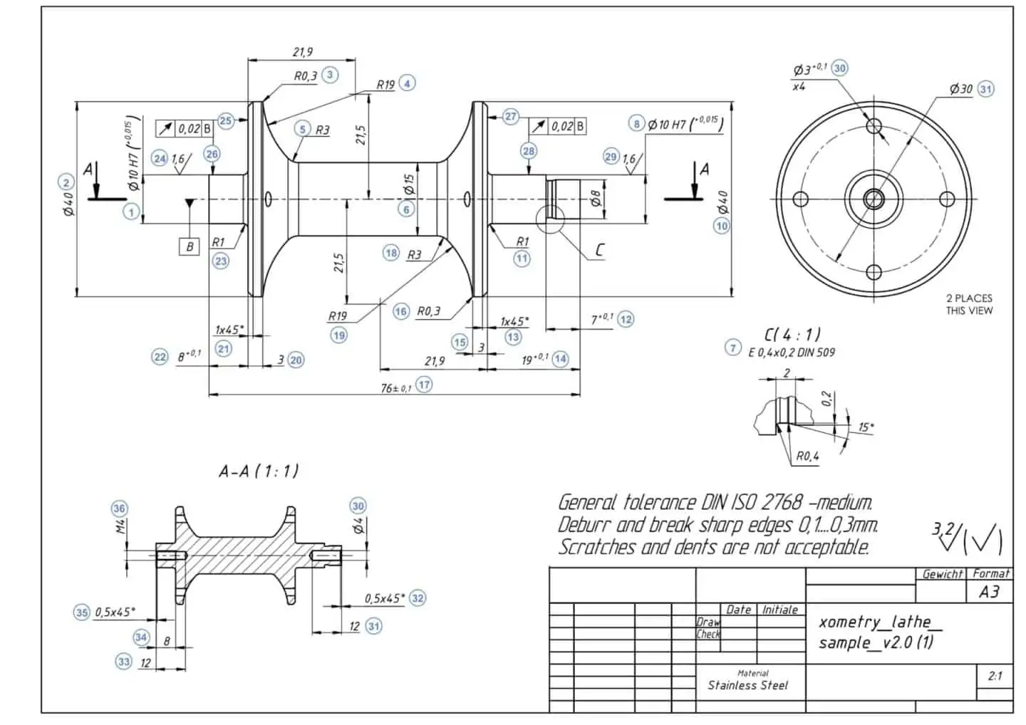
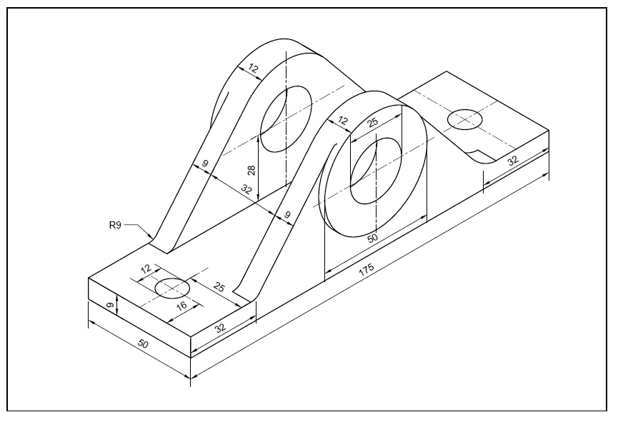
Mechanical Drawing With Dimension
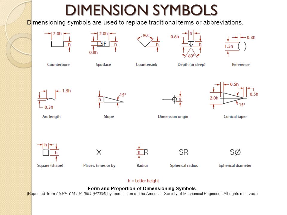
Drawing Dimension Symbols at Explore collection of

Basic Part Design Tutorial FreeCAD Documentation
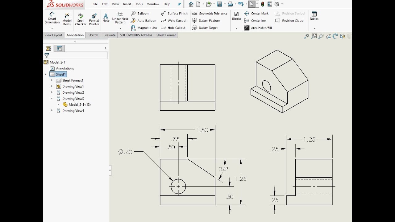
Detailed Dimension Drawing Using SolidWorks 2018 YouTube
Types Of Dimensions In Engineering Drawing at GetDrawings Free download
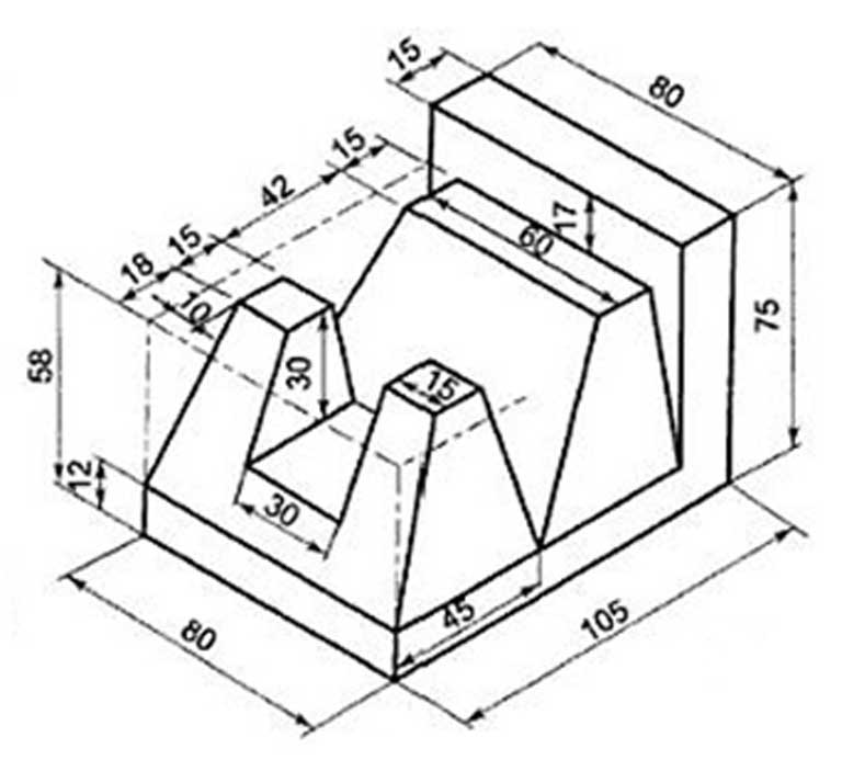
AutoCAD 3D Drawings with Dimensions for Practice 【Autocad Design PRO

can you give drawing models with dimensions to practice? GrabCAD

Detailed Dimension Drawing 5 YouTube
Engineering Drawings & GD&T For the Quality Engineer
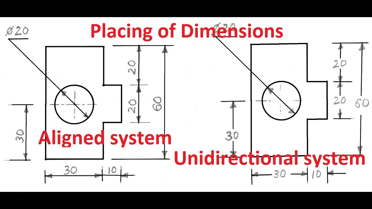
Beautiful Sketch two basic drawing dimensioning types of aligned
Dimensions And Notations Must Be Placed On The Sketch Where They Can Be Clearly And Easily Read.
In Architectural And Structural Sketches And Drawings, The Numerals Are Usually Above An Unbroken Dimension Line.
Click A Second Highlighted Drawing Entity.
Web In Machine Sketches And Drawings, In Which Fractions And Decimals Are Used For Dimensions, The Dimension Line Is Usually Broken Near The Middle To Provide Open Space For The Dimension Numerals.
Related Post: