Drawing Dimension In A Box
Drawing Dimension In A Box - (b) specifying on the drawing (or in a document referenced on the drawing) a general note such as: The base is ½” x 1 ½” square. Basic dimensions may be indicated on the drawing in the following ways: Web a very common use of reference dimensions is to provide a conversion of the length units of the drawing from either metric to inches or vice versa. I suggest you study the standard for more information. I understand it's a basic dimension but how does it control tolerance? Control dimensions in gd&t are slightly different; A feature control frame describes the conditions and tolerances of a. Adds a box around the dimension text. Web the 27mm basic dimension is based on your drawing without a tolerance, it could be anywhere on that section of the part and still meet the print. Web changes to tolerances of driving dimensions in the drawing are propagated to the model. Web 2.1.1.2 basic dimensions. (a) applying the basic dimension symbol to each of the basic dimensions. Web click the begin point for the dimensioning (or use box selection). You can set tolerance and precision options in the dimension value propertymanager, as shown in these examples. Too often they are rounded excessively and not accurate. You can use the datum identifier symbol, write the text you want inside its box, use numbering, justification etc. It is indicated on a drawing by a box around the dimension value as shown below. Web click the begin point for the dimensioning (or use box selection). Web you can group. Basic dimensions do not have conventional tolerances, Web the 27mm basic dimension is based on your drawing without a tolerance, it could be anywhere on that section of the part and still meet the print. Change the font and font size. Aligned dimensions have text placed parallel to the dimension line with vertical dimensions. Web never draw leader lines entirely. Then just remove the leader from it, by right clicking on it, and choose delete leader. If the part has multiple configurations, click configurations to change selected configurations. Web changes to tolerances of driving dimensions in the drawing are propagated to the model. Web a basic dimension is noted as a dimension with a box around it and must mathematically. Placement of all text to be read from the bottom of the drawing is called unidirectional dimensioning. The base is ½” x 1 ½” square. A rectangular box around the dimension means it is a basic dimension. When you see a number in a box, that’s a basic dimension. Basic dimensions do not have conventional tolerances, Web click the begin point for the dimensioning (or use box selection). It is indicated on a drawing by a box around the dimension value as shown below. Web changes to tolerances of driving dimensions in the drawing are propagated to the model. Web basic dimensions are typically indicated on a drawing by enclosing them in a box, which makes. Explore the full draftsight fundamentals playlist here: A rectangular box around the dimension means it is a basic dimension. In geometric dimensioning and tolerancing, basic indicates the theoretically exact value of the dimension. Placement of all text to be read from the bottom of the drawing is called unidirectional dimensioning. It is worth noting, though, that when calculating the volume. Defined in y14.5 as “a numerical value used to describe the theoretically exact size, profile, orientation, or location of a feature or datum target.” a basic dimension can be a rectilinear dimension, a diameter, an angle, etc. Placement of all text to be read from the bottom of the drawing is called unidirectional dimensioning. (b) specifying on the drawing (or. Web a basic dimension is noted as a dimension with a box around it and must mathematically relate back to the datum features. Basic dimensions are enclosed in a rectangular box & have no tolerance. On a multiview drawing, dimensions should generally be placed between adjacent views. The general guideline is that each dimension should be placed on the view. Web changes to tolerances of driving dimensions in the drawing are propagated to the model. In geometric dimensioning and tolerancing, basic indicates the theoretically exact value of the dimension. If the part has multiple configurations, click configurations to change selected configurations. Control dimensions in gd&t are slightly different; Examples of dimension tolerance and precision. Length x width x depth = volume. A feature control frame describes the conditions and tolerances of a. Web a very common use of reference dimensions is to provide a conversion of the length units of the drawing from either metric to inches or vice versa. Web basic dimensions are typically used within the gd&t framework to control the location or geometry of features. Web basic dimensions are typically indicated on a drawing by enclosing them in a box, which makes them easily distinguishable from traditional dimensions. Web can anyone tell me the true definition of a box dimension on a mechanical drawing? Adds a box around the dimension text. Gd&t is a way of describing the dimensions and tolerances that’s different from traditional coordinate measurement plus/minus tolerancing. Basic dimensions do not have conventional tolerances, Then just remove the leader from it, by right clicking on it, and choose delete leader. Reference dimension — a numerical value enclosed in parentheses, provided for information only. If the part has multiple configurations, click configurations to change selected configurations. Web never draw leader lines entirely horizontal or vertical. But having even one positional gd&t tolerance on a drawing will necessitate datums. A number in a box denotes a basic dimension. Basic dimensions are enclosed in a rectangular box & have no tolerance.
Box Drawing How To Draw A Box Step By Step
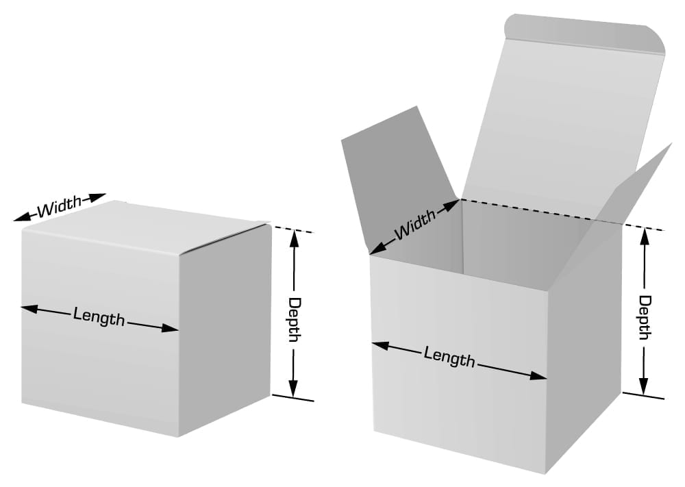
Box Dimension Guidelines for Packaging TPS Printing
Box Drawing How To Draw A Box Step By Step

How to Draw a Box Step by Step Drawing Sketch YouTube
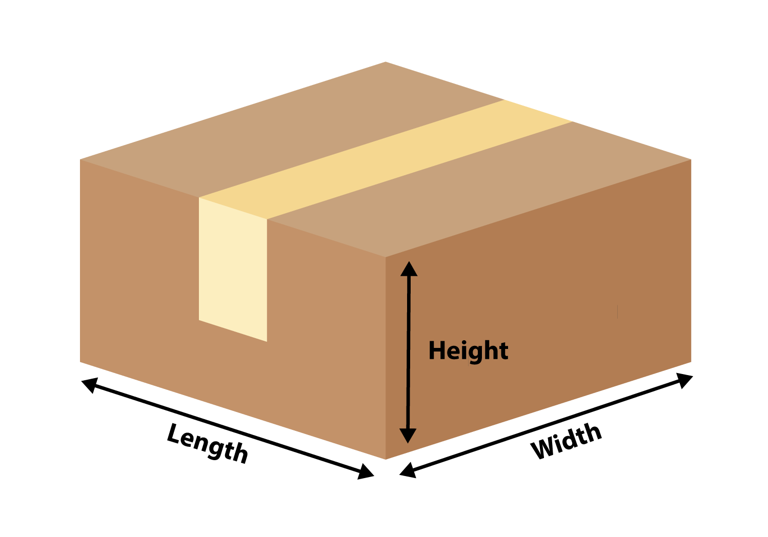
How to Measure Box Sizes The Ultimate Guide

How to Dimension a box final Printex Transparent Packaging
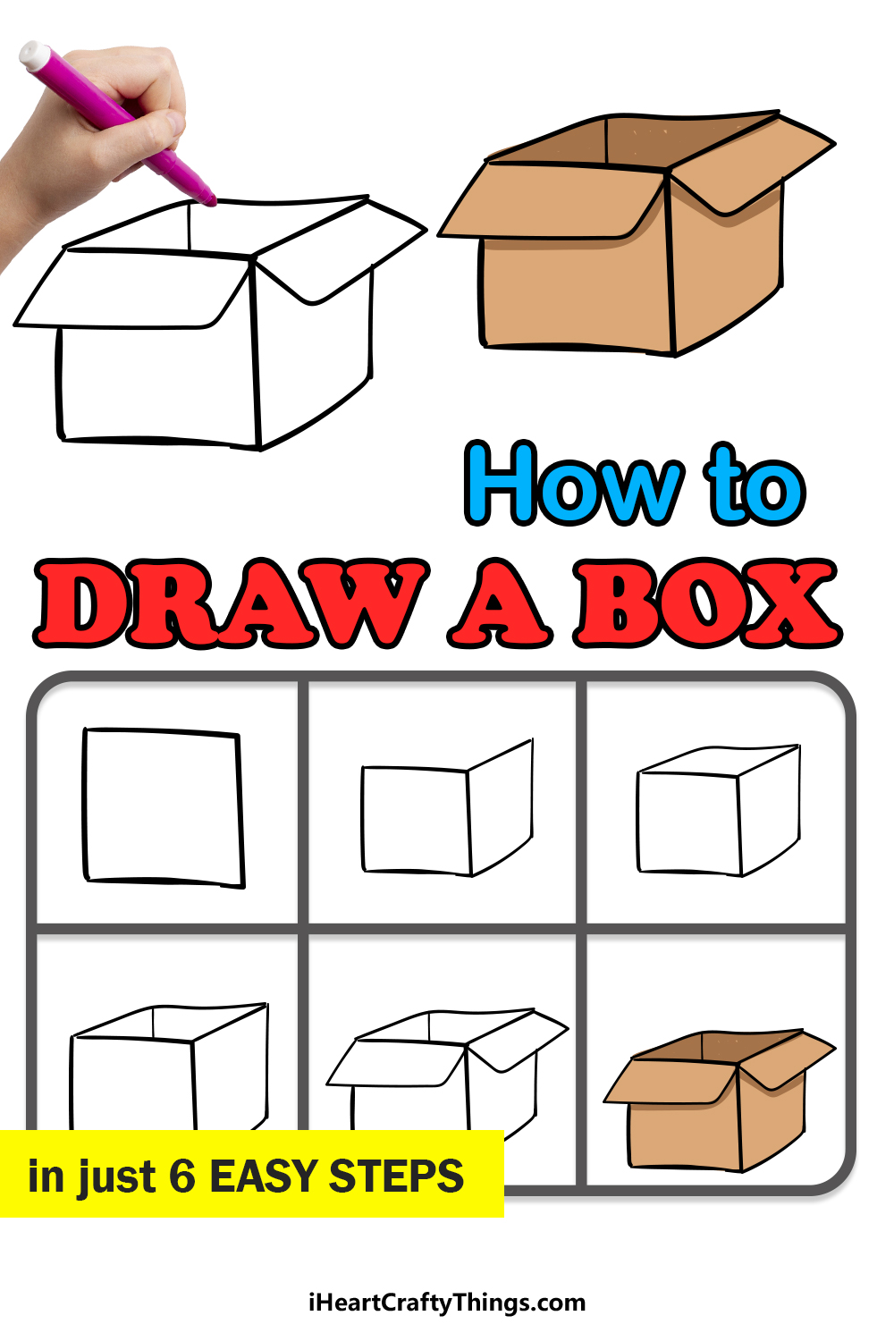
Box Drawing How To Draw A Box Step By Step
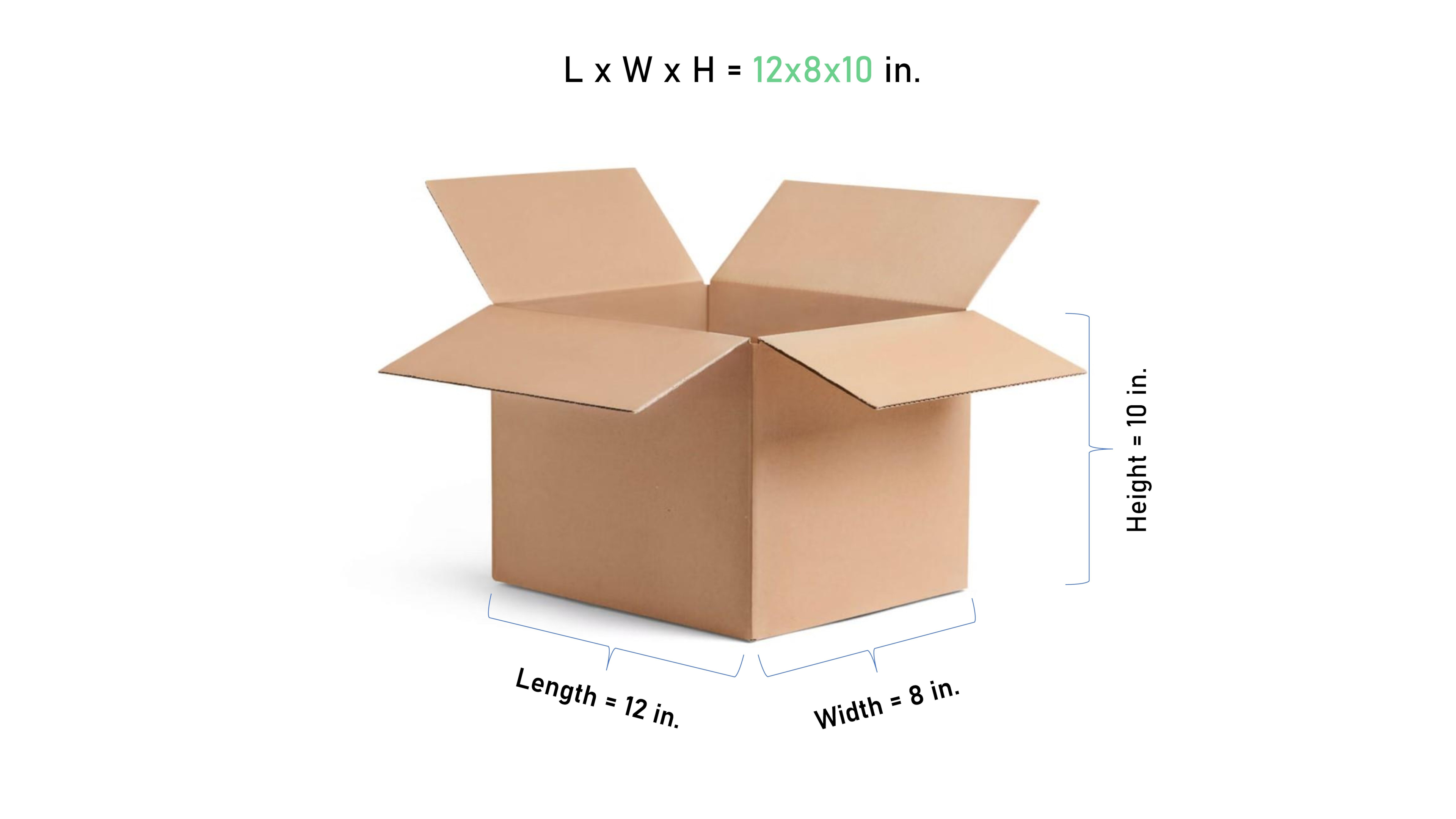
How to Read Box Dimensions? A Guide to Box Packaging Packoi

Detailed Dimension Drawing Using SolidWorks 2018 YouTube
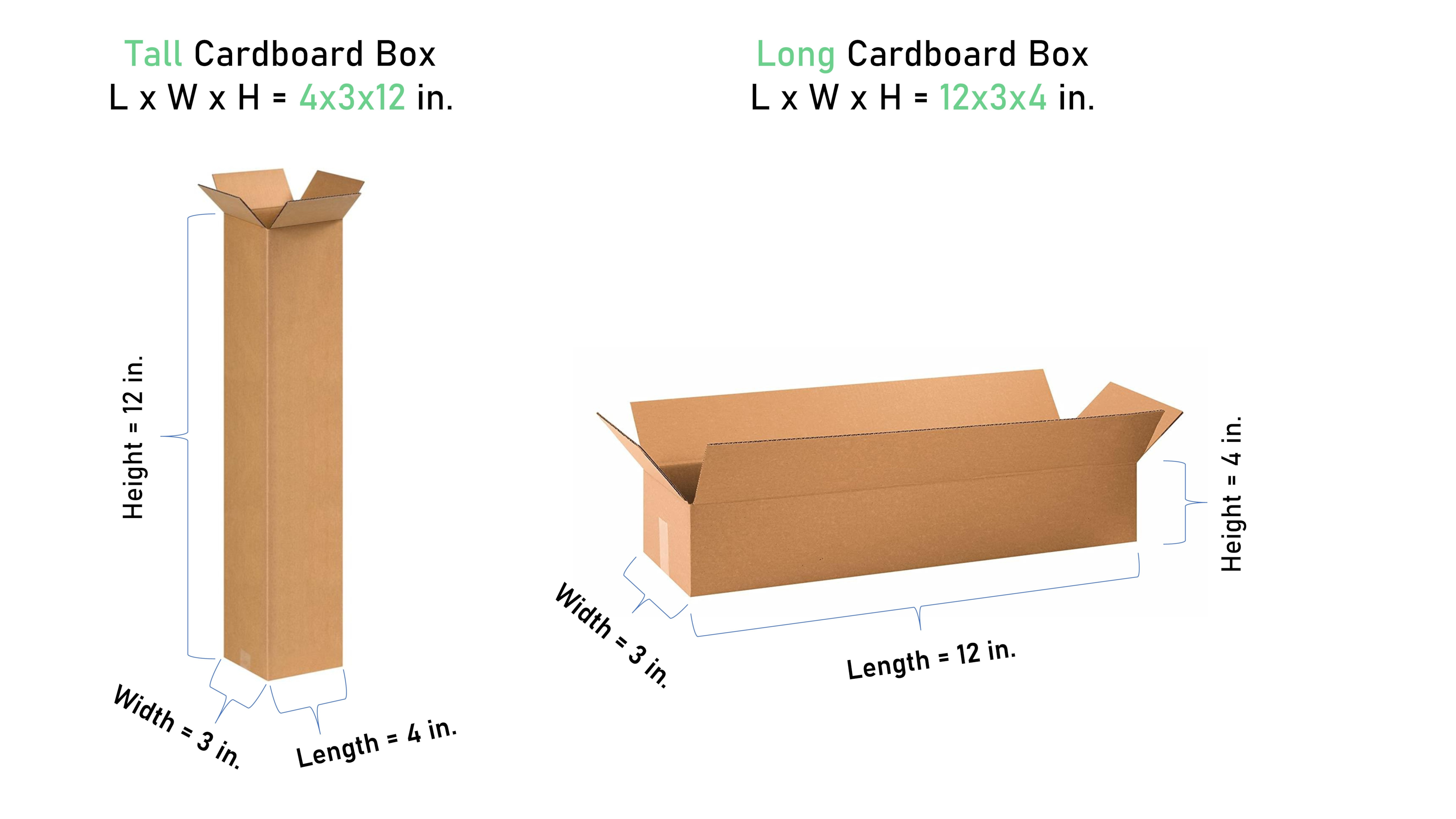
How to Read Box Dimensions? A Guide to Box Packaging Packoi
(B) Specifying On The Drawing (Or In A Document Referenced On The Drawing) A General Note Such As:
On A Multiview Drawing, Dimensions Should Generally Be Placed Between Adjacent Views.
Dimension Bounding Boxes Help You To Align The Dimensions Of Assembled Entities Along The Box Margins At Defined Offsets.
You Can Set Tolerance And Precision Options In The Dimension Value Propertymanager, As Shown In These Examples.
Related Post: