Engineering Drawing Circle Dimensions
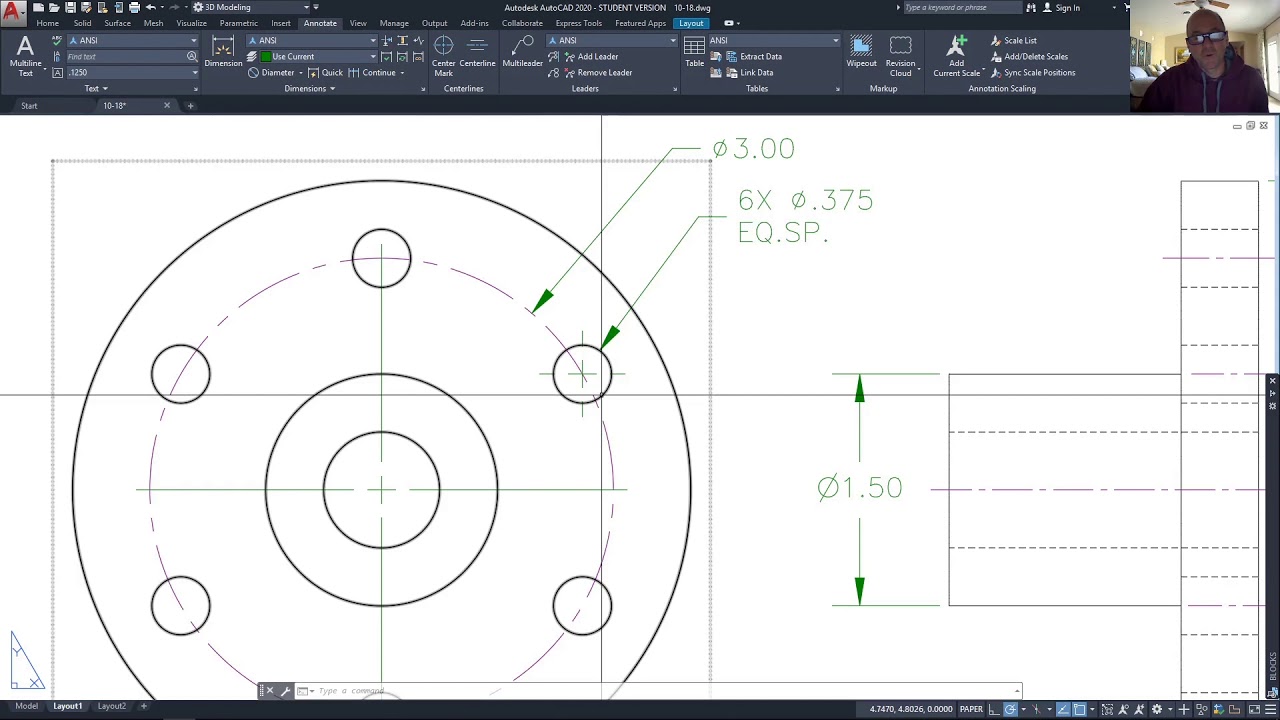
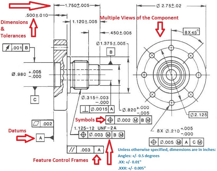
Engineering Drawing Circle Dimensions - Web basic dimensioning is the addition of only functional size values to drawing entities. Aligned dimensions have text placed parallel to the dimension line with vertical dimensions. Web compass is used to draw an arc or circle with known dimensions on engineering drawing. Vertical — the up and down distance relative to the drawing sheet.here the height and the depth are both vertical dimensions, even though they are in two different directions on the part.; The ⓔ is one of the options in the feature control frame as defined in the iso 8015 standard, or asme y14.5m. (1) analyze the function of part structure shape and understand the combination relationship with adjacent parts; Web as basic dimensions are perfect, there would be no deviations, and they would not be recorded on the report. Dimensions should be placed strategically to avoid crossing extension lines, unless doing so would clutter the drawing or move the dimension too far away from the feature being dimensioned. Starting point of running dimensioning or coordinate dimensioning. If the isometric drawing can show all details and all dimensions on one drawing, it is ideal. A circle is dimensioned by its diameter and an arc by its radius using a leader line and a note. Instead of basic dimensions, we would report the following: The ⓔ is one of the options in the feature control frame as defined in the iso 8015 standard, or asme y14.5m. Their basic purpose is to show circular/cylindrical features in. Web essentially, dimensioning refers to the process of specifying the exact size, shape, and location of different parts and features on an engineering drawing. One leg contains needle at the bottom and other leg contains a ring in which a pencil is placed. Ala hijazi engineering working drawings basics page 10 of 22. If a hole goes completely. Working drawings. The drilled through hole is ∅5/8”. Two methods of dimensioning are in common use. In mechanical engineering drawings, linear dimensions are classified in size, distances and radii (iso/tr 14638). The dimensions are 3” long, 2 1/8” wide, 1 5/8” high with a 45 angle ½” deep. Dimensioning is vital in the engineering industry as it ensures that the final product. It is generally made of steel and consists two legs. Web basic dimensioning is the addition of only functional size values to drawing entities. (2) distinguish the primary and secondary dimensions, determine the design basis and mark the main dimensions; The depth of a blind hole may be specified in a note and is the depth of the full diameter. One leg contains needle at the bottom and other leg contains a ring in which a pencil is placed. Diameter—the full distance across a. Aligned dimensions have text placed parallel to the dimension line with vertical dimensions. The needle tip is placed at the respected point and pencil tip is adjusted to the height at least 1mm just. Figure 1. 6.the dimension value must be placed approximately 2 mm above the dimension line. A circle is dimensioned by its diameter and an arc by its radius using a leader line and a note. Instead of basic dimensions, we would report the following: (2) distinguish the primary and secondary dimensions, determine the design basis and mark the main dimensions; If the. Common examples of such features include bolt holes, pins, discs, etc. In mechanical engineering drawings, linear dimensions are classified in size, distances and radii (iso/tr 14638). Working drawings need tolerances in addition to functional size values. Web on a multiview drawing, dimensions should generally be placed between adjacent views. Web dimensioning rules for holes: A circle is dimensioned by its diameter and an arc by its radius using a leader line and a note. Web centerlines are one of the most frequently used tools in engineering drawing. The dimensions are 3” long, 2 1/8” wide, 1 5/8” high with a 45 angle ½” deep. Web gd&t flatness is a common symbol that references how. One leg contains needle at the bottom and other leg contains a ring in which a pencil is placed. Web essentially, dimensioning refers to the process of specifying the exact size, shape, and location of different parts and features on an engineering drawing. Asme (ansi) y14.5m is the standard for. The flatness tolerance references two parallel planes (parallel to the. Indication signifying the extremities of a dimension or leader line. Methods and steps for dimensioning parts. Starting point of running dimensioning or coordinate dimensioning. Instead of basic dimensions, we would report the following: The angle begins as the midpoint of the 3” long dimension. In the example above, the 120 degree callout and the 42 diameter bolt circle are the basic dimensions and the true position of 0.2 is the. Working drawings need tolerances in addition to functional size values. Web dimensioning rules for holes: Instead of basic dimensions, we would report the following: The depth of a blind hole may be specified in a note and is the depth of the full diameter from the surface of the object. Vertical — the up and down distance relative to the drawing sheet.here the height and the depth are both vertical dimensions, even though they are in two different directions on the part.; The needle tip is placed at the respected point and pencil tip is adjusted to the height at least 1mm just. If a symbol dimension is shown as 1.5h, and the predominant character height on the drawing is to be 3mm, then the symbol dimension is 4.5mm (1.5 x 3mm). The angle begins as the midpoint of the 3” long dimension. It is generally made of steel and consists two legs. (2) distinguish the primary and secondary dimensions, determine the design basis and mark the main dimensions; Web note 1 to entry: A complete understanding of the object should be possible from the drawing. If a hole goes completely. The flatness tolerance references two parallel planes (parallel to the surface. Extension lines are used to connect the dimension line to the visible.
Lecture Notes Engineering Drawing Part 4
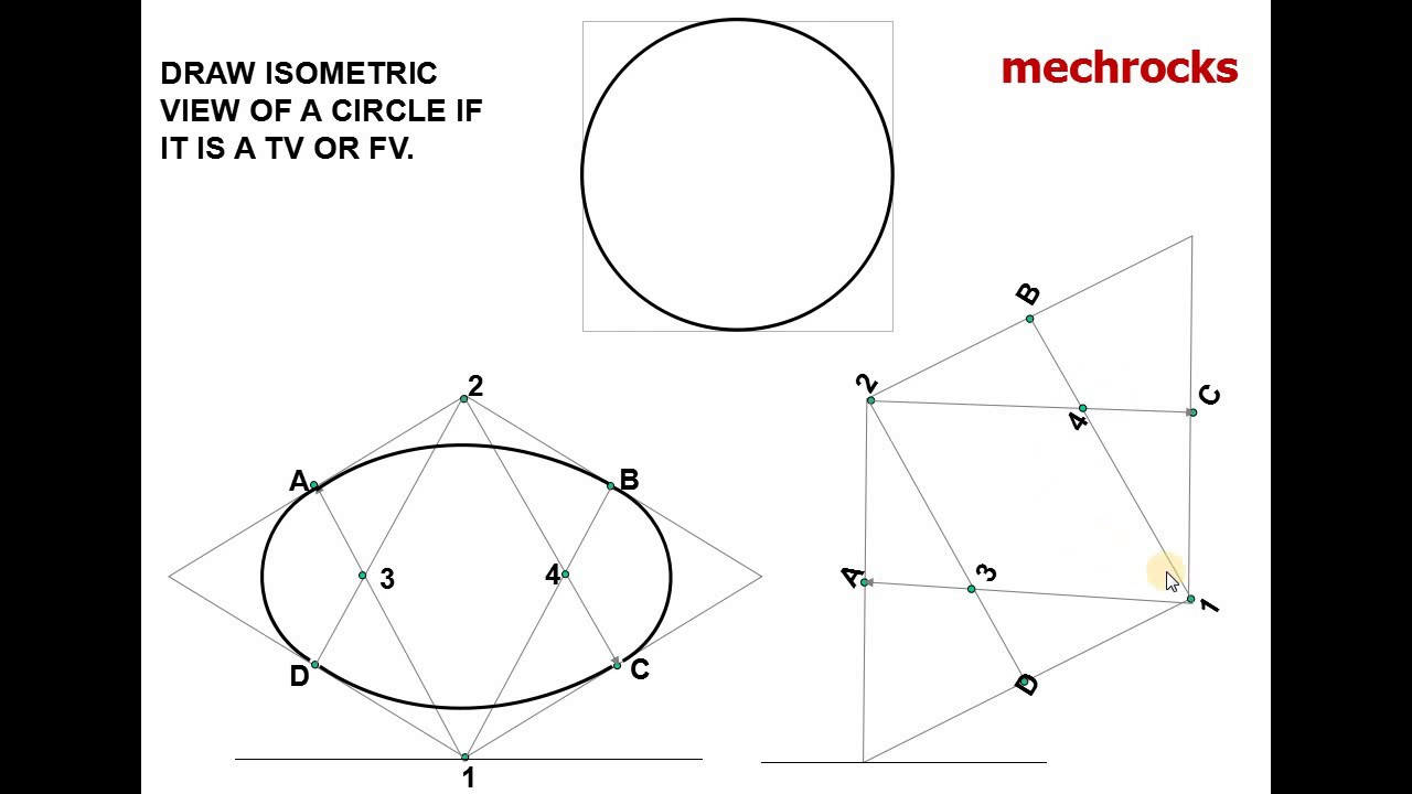
Engineering Drawing How to Draw Isometric view of a Circle YouTube

How to draw Hexagon around the circle engineering drawing
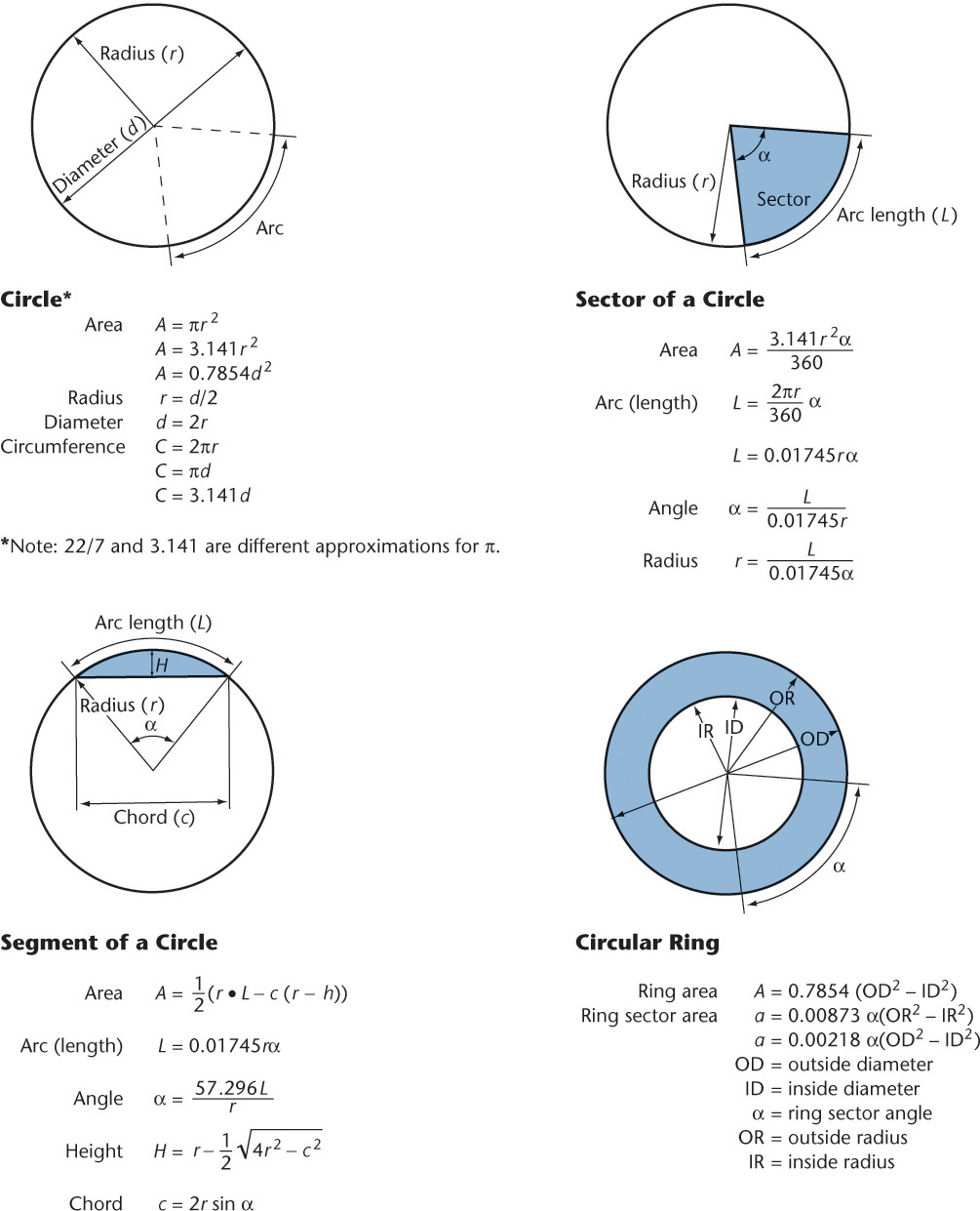
Appendices Technical Drawing with Engineering Graphics, 15th Edition
Dimensioning A Circle

Beginner's Guide to Basic Dimensions Machinist Guides
Dimension Symbols Of Drawing at GetDrawings Free download
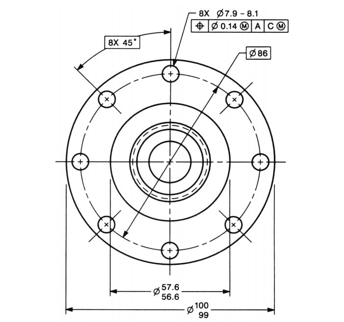
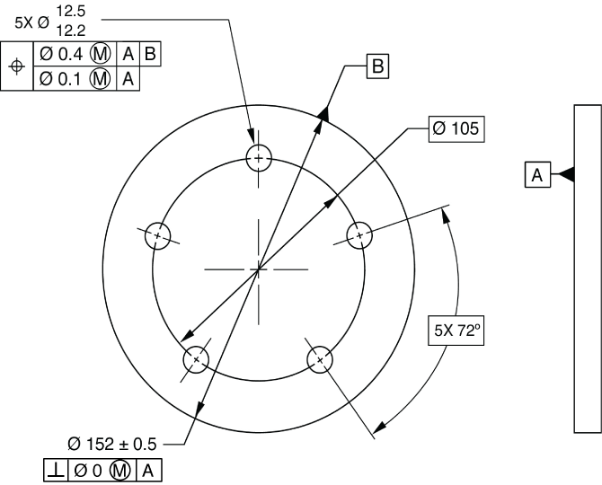
Dimensioning Circular Features and Other Dimensioning Tips & Tricks in
Types Of Dimensions In Engineering Drawing at GetDrawings Free download

How to make a Isometric Circle Engineering Drawing Isometric
Web Basic Dimensions Are Used For Calculations.
Dimension Lines Are Used To Indicate The Size And Location Of Features In An Engineering Drawing.
Ala Hijazi Engineering Working Drawings Basics Page 10 Of 22.
Different Types Of Features Require Unique Methods Of Dimensioning.
Related Post: