Engineering Scales For Drawing
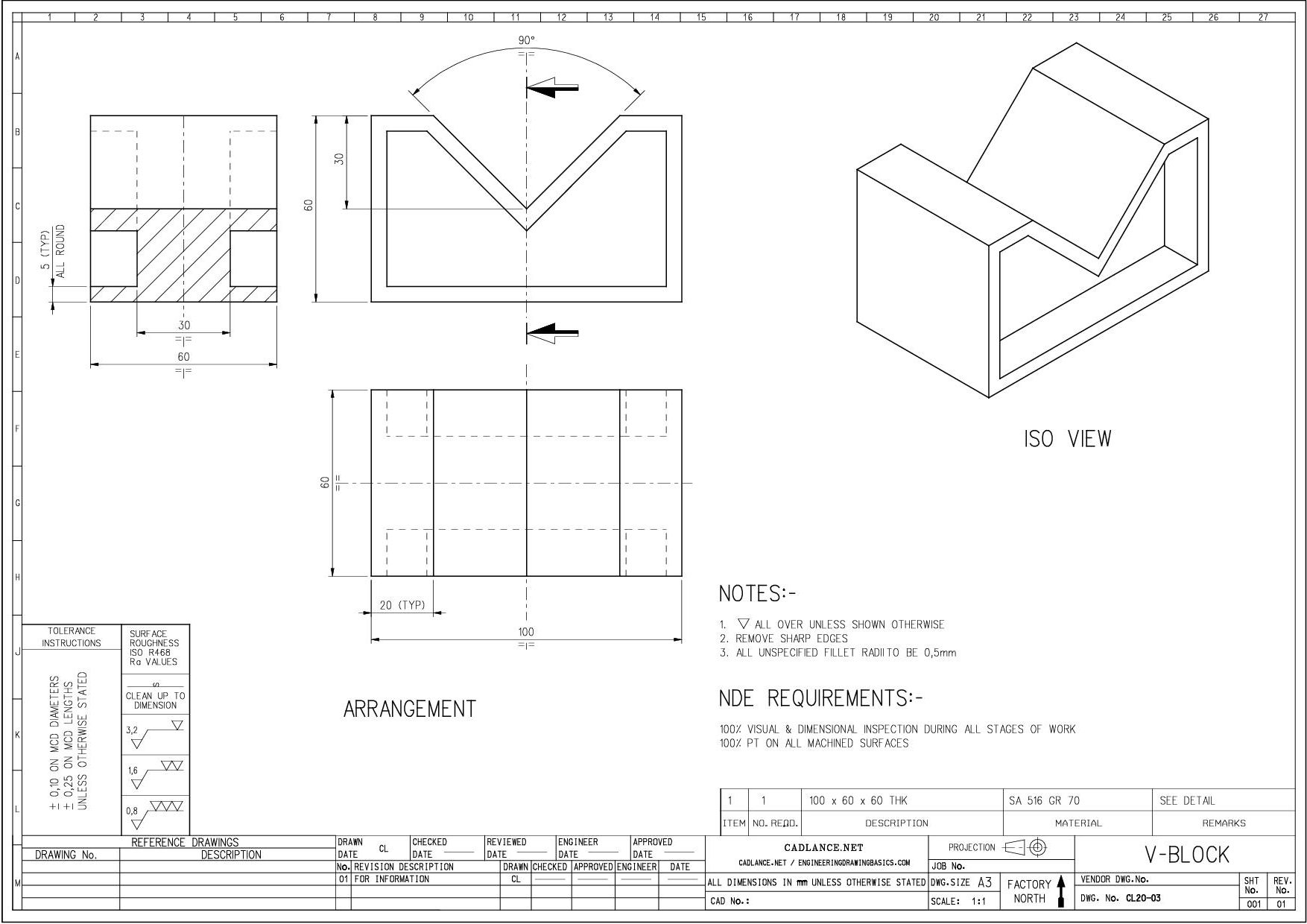
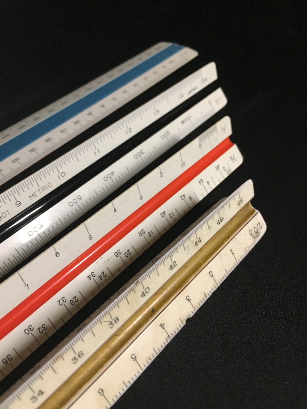
Engineering Scales For Drawing - In this post we will be exploring architectural scales and scale drawings. Design & documentation > construction documentation. Engineering scale ruler read & create engineering drawings. Web once we know the drawing scale, we can use a scale ruler to determine the measurement shown on the drawing in real life. They are designed to let the drafter draw scale drawings without having to convert from full scale to a different scale. For instance, when drawing a door in cad, the door would be 3 feet wide and 7 feet tall. A scale is the ratio of the linear dimension of an object’s element as shown in a drawing to the actual dimensions of the same object’s element. It is a very common tool used for measuring things in land development and site construction plans. • diagonal scales are used to measure distances in a unit and its immediate two subdivisions; Web in this detailed guide on different types of scales in engineering drawing, we will discuss engineering drawing scales and their designation for use on all technical drawings in any field of engineering. Web there are 2 types of drafting scales used in design and construction: You can even find a metric scale if that’s what you need. Web types of scales used in engineering drawing. It is a very common tool used for measuring things in land development and site construction plans. Most models of engineering scales are available either in 4,. Or, a scale is a measuring device that is used to determine a person’s weight. In this post we will be exploring architectural scales and scale drawings. A scale is the ratio of the linear dimension of an object’s element as shown in a drawing to the actual dimensions of the same object’s element. Web professional drafting scales, engineering scales,. Web professional drafting scales, engineering scales, and architectural scales can come in a number of sizes and models. Most cad systems allow the drafter to draw at whatever scale he or she feels like. Web scales are precision instruments with fine graduations or marks. However, if fabrication shops are going to be using your drawings you will help them far. • diagonal scales are used to measure distances in a unit and its immediate two subdivisions; Web types of scales used in engineering drawing. Architectural scale is commonly used in building design and construction. Most models of engineering scales are available either in 4, 6” or 12” sizes, but larger engineering rulers are. They are designed to let the drafter. A beginner's look at how to read and use an engineer's scale. Web how to read an engineers scale (mostly used for roads and topographical measurements) engineer scales, such as 1˝ = 10´ or 1˝ = 50´ how to read a metric scale (mostly used for buildings in other parts of the world) how to determine the scale of a. This means that every 1/4 inch on the drawing represents 1 foot in real life. Web once we know the drawing scale, we can use a scale ruler to determine the measurement shown on the drawing in real life. Web description of how (and a calculator) to convert drawings from one architectural or engineering scale to another. A beginner's look. Design & documentation > construction documentation. Web professional drafting scales, engineering scales, and architectural scales can come in a number of sizes and models. Most cad systems allow the drafter to draw at whatever scale he or she feels like. Web these scales are often used for taking measurements off scaled architectural or engineering drawings. Architectural scale is commonly used. Web once we know the drawing scale, we can use a scale ruler to determine the measurement shown on the drawing in real life. When a standard scale is not suitable to be used for a detail or assembly, a non standard scale may be used and should be. Web what is scale in engineering drawing? Design & documentation >. Dm, cm & mm, or yard, foot & inch. A scale is the ratio of the linear dimension of an object’s element as shown in a drawing to the actual dimensions of the same object’s element. An actual length of 1 cm is measured on a 1:50 blueprint floor plan. Web an architect’s scale is typically used for smaller or. Learn how to read the various scales and then how to use the scale on a couple of simple examples. Or, a scale is a measuring device that is used to determine a person’s weight. Web these scales are often used for taking measurements off scaled architectural or engineering drawings. When a standard scale is not suitable to be used. Dm, cm & mm, or yard, foot & inch. Most models of engineering scales are available either in 4, 6” or 12” sizes, but larger engineering rulers are. Web types of scales used in engineering drawing. Web how to read an engineers scale (mostly used for roads and topographical measurements) engineer scales, such as 1˝ = 10´ or 1˝ = 50´ how to read a metric scale (mostly used for buildings in other parts of the world) how to determine the scale of a drawing where the scale isn’t indicated Where the denominator is the number after the colon. Say your drawing is a floor plan at 1:100 and we want to know how big the internal bathroom is. Engineer, or civil, scales, such as 1 ̋ = 10 ́ or 1 ̋ = 50 ́, are used for measuring roads, water mains and topographical features. Web if a drawing is drawn to scale, it can be used to obtain information such as physical dimensions, tolerances, and materials that allows the fabrication or construction of the component or system. Web in this detailed guide on different types of scales in engineering drawing, we will discuss engineering drawing scales and their designation for use on all technical drawings in any field of engineering. For simplicity and clarity, cad users draw buildings at full scale. Multiply the measurement on the drawing with the denominator; • diagonal scales are used to measure distances in a unit and its immediate two subdivisions; This means that every 1/4 inch on the drawing represents 1 foot in real life. Web what is scale in engineering drawing? A beginner's look at how to read and use an engineer's scale. If a large part needs to be documented on a small piece of paper it can be scaled down by an appropriate amount.
Engineering Scales and Equivalents Chart Convert to Autocad

PREMIUM 12 inch Triangular Engineer Scale Ruler Anodized Solid Aluminum
Mechanical Drawing Scales Tutorial Engineering Drawing Basics

Understanding Scales and Scale Drawings A Guide

Office Technical Drawing Supplies Triangular Scales 6 Architect
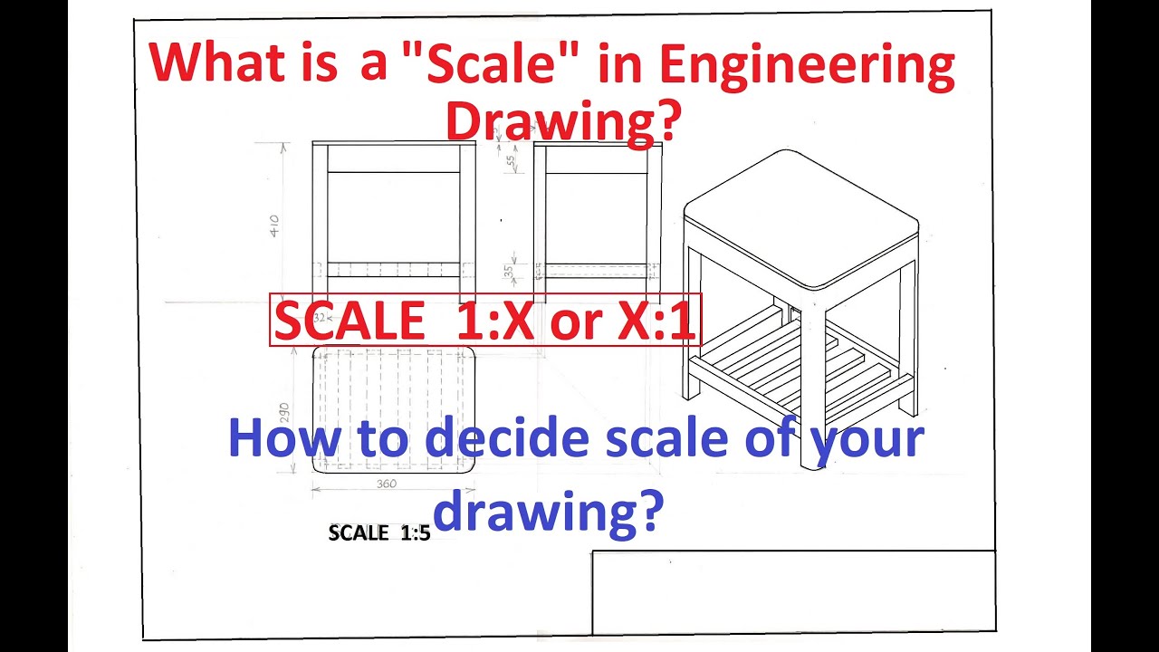
1.8What is a "Scale" in Engineering Drawing? How to decide scale of

plain scale in engineering drawing scales in engineering drawing

Brand New Triangular Scales Engineer Drafting Ruler Aluminum Scale

BTSKY 3 Pack 12" Architectural & Engineering Scale Rulers with Standard
20+ Drafting Drawing Scale Chart Gif Complete Education
The Classic Triangular Scale Is Still A Popular Tool, And There Are Two Models — One For Architects And One For Engineers.
In This Post We Will Be Exploring Architectural Scales And Scale Drawings.
Most Cad Systems Allow The Drafter To Draw At Whatever Scale He Or She Feels Like.
Web There Are 2 Types Of Drafting Scales Used In Design And Construction:
Related Post: