One Line Drawing Electrical
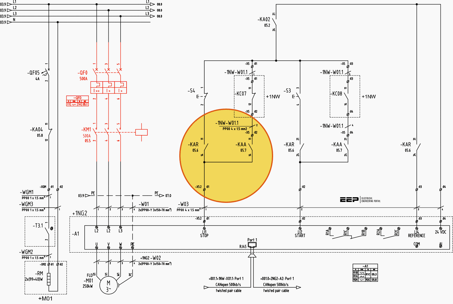
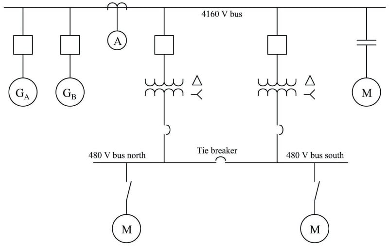
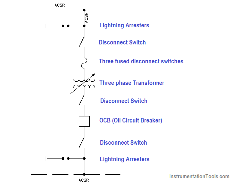
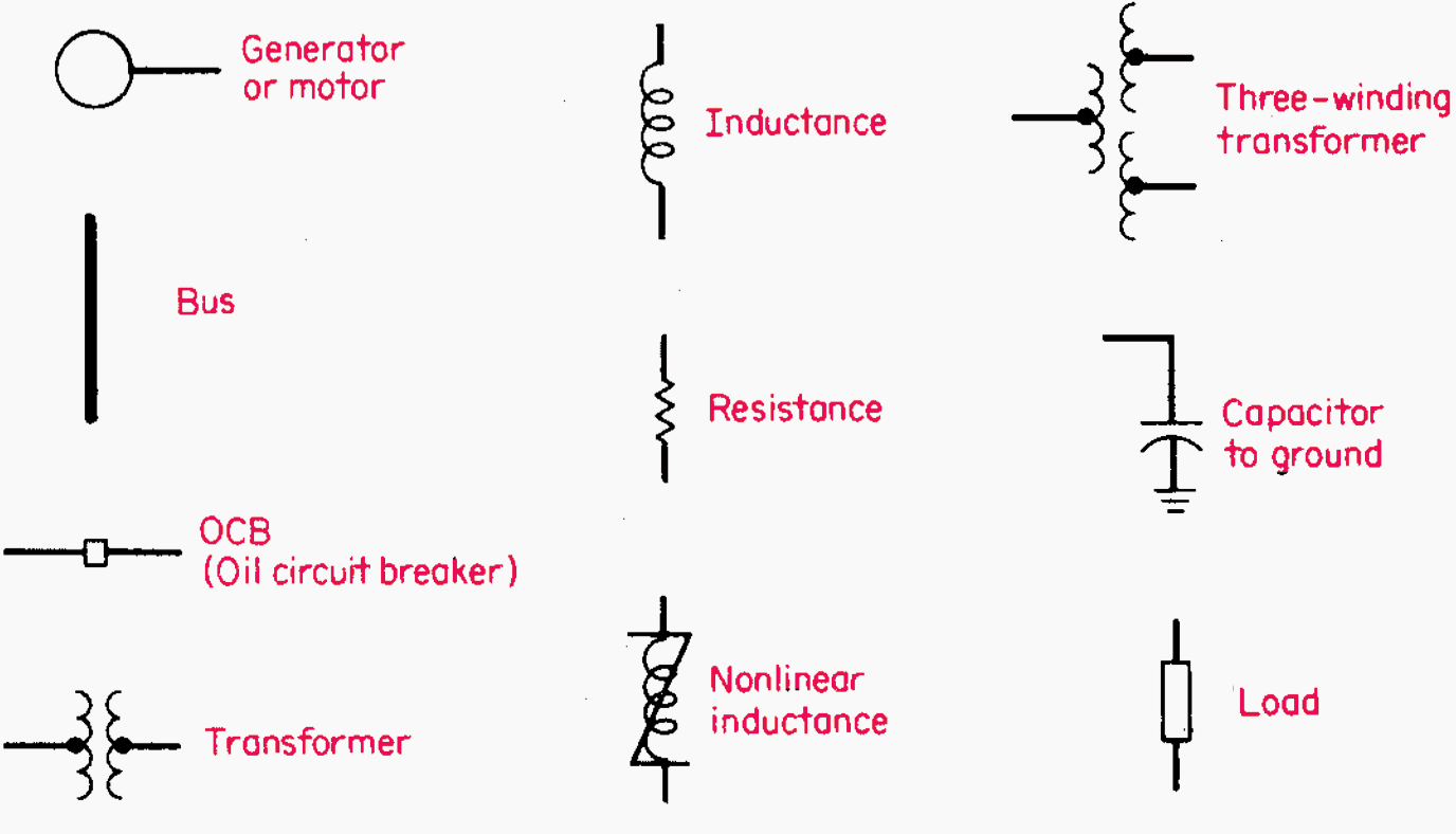
One Line Drawing Electrical - Relays (function, use and type) is required to be mentioned. Web the selected base s value remains constant throughout the system, but the base voltage is 13.8 kv at the generator and at the motors, and 72.136 kv on the transmission line. A single line can show all or part of a system. Usually they are given in form of electrical circuits between two lines which are representing control voltage potentials. It is a powerful tool used by engineers to design and analyze the electrical systems. Web in electrical engineering, a single line diagram is a simplified representation of an electrical power system or electrical grid that shows the flow of electricity through the system. Line diagram is used to show the relationship between circuits and their components but not the actual location of the components. Drag and drop symbols to the circuits and connect them. Line (ladder) diagram is a diagram that shows the logic of an electrical circuit or system using standard symbols. Symbols and lines are used to represent the nodes and connections in the system, and electrical characteristics may be included as well. A single line can show all or part of a system. Web single line diagram (sld) we usually depict the electrical distribution system by a graphic representation called a single line diagram (sld). Main components such as transformers, switches, and breakers are indicated by their standard graphic symbol. This diagram shows the flow of electrical power from the source to. Web making wiring or electrical diagrams is easy with the proper templates and symbols: The single lines represent the connection between components, or the. A single line can show all or part of a system. We will looking a normal set of plans o. Web by the end of this video will completely understand the ideals of the one line. Line (ladder) diagram is a diagram that shows the logic of an electrical circuit or system using standard symbols. Symbols and lines are used to represent the nodes and connections in the system, and electrical characteristics may be included as well. No calculation is necessary for correcting the value of the generator reactance because it is given as 0.15 p.u.. A diagram which shows, by means of single lines and graphic symbols, the course of an electric circuit or system of circuits and the component devices or parts used therein. Line (ladder) diagram is a diagram that shows the logic of an electrical circuit or system using standard symbols. Since then, no team had ever had more than four in. It is a simplified drawing of the whole system or a portion of the power system that shows the electrical placement of all major equipment. A diagram which shows, by means of single lines and graphic symbols, the course of an electric circuit or system of circuits and the component devices or parts used therein. Symbols and lines are used. [1] [2] a single line in the diagram typically corresponds to more than one physical conductor: Web may 8th, 2024 2 3. Web one of the key tools in developing and documenting an electrical power system is the single line diagram (shortened sld). It will have one single line shown for bus (or cable) to represent all three phases. Symbols. This condenses the space and complexity of the diagram for simpler troubleshooting. Usually they are given in form of electrical circuits between two lines which are representing control voltage potentials. Web may 8th, 2024 2 3. As the name suggests, a single line is used to denote the multiple power. Web we usually depict the electrical distribution system by a. Electrical single line diagram guidance_version 1.0_november 2021. There’s also a lot more stuff so check out the rest of this blog. As the name suggests, a single line is used to denote the multiple power. The fault current clearing time setting is required to be achieved from inverse definite minimum time (idmt) relay or over current relay (ocr) of the. A diagram which shows, by means of single lines and graphic symbols, the course of an electric circuit or system of circuits and the component devices or parts used therein. A single line can show all or part of a system. We will looking a normal set of plans o. This condenses the space and complexity of the diagram for. This condenses the space and complexity of the diagram for simpler troubleshooting. A single line can show all or part of a system. Symbols and lines are used to represent the nodes and connections in the system, and electrical characteristics may be included as well. Drag and drop symbols to the circuits and connect them. The fault current clearing time. Web the selected base s value remains constant throughout the system, but the base voltage is 13.8 kv at the generator and at the motors, and 72.136 kv on the transmission line. It will have one single line shown for bus (or cable) to represent all three phases. As the newest member of plano's clean fleet, this vehicle will be able to collect from 1,100 homes on a single charge. Web one of the key tools in developing and documenting an electrical power system is the single line diagram (shortened sld). Unlike single line diagrams, every drawn line matches one single wire which actually exists inside control part of the. Drag and drop symbols to the circuits and connect them. Windows terminal is back with another preview release! Relays (function, use and type) is required to be mentioned. The fault current clearing time setting is required to be achieved from inverse definite minimum time (idmt) relay or over current relay (ocr) of the vacuum circuit breaker (vcb) panel. Electrical power grids primarily consist of. This diagram shows the flow of electrical power from the source to various devices, such. It is used by electricians, engineers, and technicians to understand the electrical components and connections within a system. Web we usually depict the electrical distribution system by a graphic representation called a single line diagram (sld). Web by the end of this video will completely understand the ideals of the one line diagram from a electrical perspective. Usually they are given in form of electrical circuits between two lines which are representing control voltage potentials. It is a powerful tool used by engineers to design and analyze the electrical systems.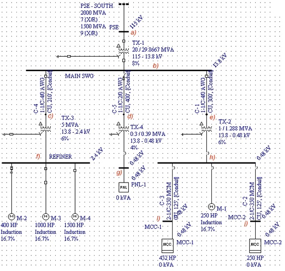
Electrical Single Line Diagram Part Two Electrical Knowhow
how to prepare electrical single line diagram Wiring Diagram and
Electrical Single Line Diagram Part Two Electrical Knowhow
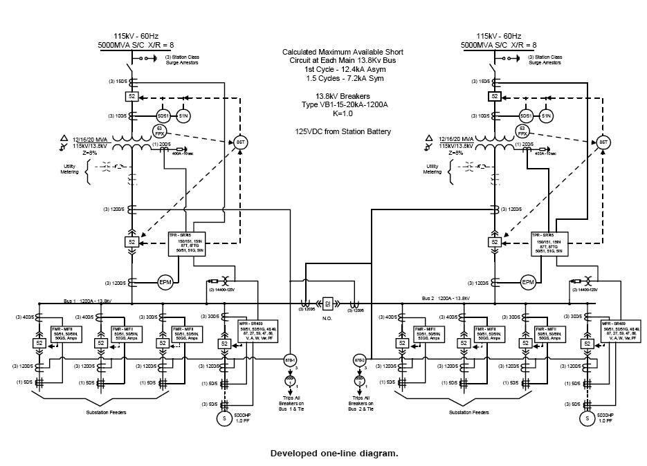
Learn to read and understand single line diagrams & wiring diagrams EEP
Singleline Electrical Diagrams Electric Power Measurement and
how to prepare electrical single line diagram Wiring Diagram and
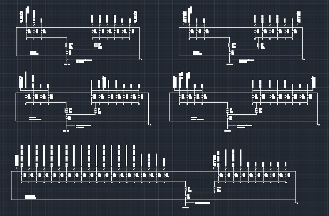
Electrical Single Line Diagram Template (DWG) — LINE DRAW CAD LAB

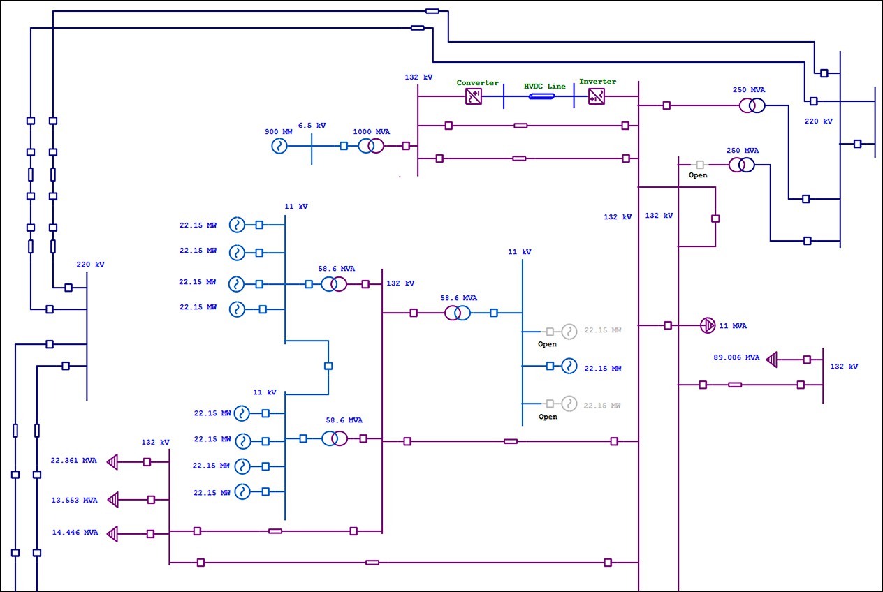
Single Line Diagram of Power Plant Power Systems
How To Calculate and Draw a Single Line Diagram For The Power System EEP
Electrical SingleLine Diagram Intelligent One Line Diagram ETAP
Visit Plano.gov/Cleanfleet For More Info On The Environmentally Friendly Cars Within The City's Vehicle Fleet.
We Will Looking A Normal Set Of Plans O.
Line Diagrams Provide A Fast, Easy Understanding Of The Connections And Use Of.
Power Generation Symbols Are Used In The Single Line Diagram To Depict The Major.
Related Post: