Parallelism Drawing
Parallelism Drawing - Web gd & t. Facilitate the dimensioning of drawings. It is also used to denote the measurement of how far these features deviate from this ideal condition on an actual part. It is just the extension of angularity tolerance with specific control on angle of orientation. However, this would require the use of basic dimensions. Web parallelism tolerance in gd&t is a type of orientation control tolerance that controls the parallelism of two lines, surfaces, or axis. Web drawing in parallel perspective. Faces or axes) to be geometrically parallel to one another. Parallelism is an orientation control. The short answer is yes, that is a bad practice. Web drawing in parallel perspective. Web the technique called section views is a very important aspect of design and documentation. Web parallelism is a 3d gd&t orientation tolerance which maintains that two part features are parallel to each other. But it creates a tolerance zone of two parallel planes where all. It is just the extension of angularity tolerance with. For mechanical drawings section views are used to reveal interior features of. Ignacio asked us if it is a bad practice to reference three datums in a single drawing callout for the parallelism symbol. Another way to call out these holes would be to use a position tolerance. Geometric tolerances are specified using symbols on a drawing. In mechanical part. Web parallelism is the geometrical condition of a surface or center plane equidistant at all points from a datum plane, or an axis. Web parallelism tolerance in gd&t is a type of orientation control tolerance that controls the parallelism of two lines, surfaces, or axis. The distance between the parallel lines, or surfaces, is specified by the geometric tolerance zone.. Web parallelism as a gd&t term is a requirement for two features (e.g. Another way to call out these holes would be to use a position tolerance. Perfect parallelism occurs when a surface is exactly parallel to a datum. Web parallelism occurs when one or more sentences contain two or more elements with the same grammatical or conceptual structure. Let’s. In this case it is 180 deg. Web parallelism as a gd&t term is a requirement for two features (e.g. We can identify these lines using angles and symbols in diagrams. In this type of drawing, edges and surfaces that are parallel in the physical model are also parallel in the drawing. Parallel simply means that the distances between the. In mechanical part drawings, parallelism tolerance allows the designer to specify the degree to which a feature ‘s orientation may vary with respect to its referenced datum by creating a tolerance zone parallel to that datum. In this case it is 180 deg. Web parallelism callout on drawings. Geometric tolerances are specified using symbols on a drawing. Perfect parallelism occurs. Position would simultaneously control location and orientation. 23k views 5 years ago graphic design & technical drawing. The distance between the parallel lines, or surfaces, is specified by the geometric tolerance zone. Gd&t ( geometrical dimensions and tolerances ) is the new vocabulary of engineering drawings. Currently, we have 16 symbols for geometric tolerances, which are categorized according to the. Another way to call out these holes would be to use a position tolerance. Lebron james hoes fu*king up their husband's legacy : Web by gd&t basics on february 12, 2021. Classification and symbols of geometric tolerance characteristics. In this case it is 180 deg. Parallelism is an orientation control. Parallelism controls the surface, midplane or axis which need to be in parallel or 180deg with respect the datum surface. Web parallelism is a 3d gd&t orientation tolerance which maintains that two part features are parallel to each other. Youtuber bashes lebron james' wife savannah james while drawing ayesha curry and jada pinkett parallel Using. Gd&t ( geometrical dimensions and tolerances ) is the new vocabulary of engineering drawings. April 8, 2023 fact checked. Web parallelism is the geometrical condition of a surface or center plane equidistant at all points from a datum plane, or an axis. Web parallelism is a 3d gd&t orientation tolerance which maintains that two part features are parallel to each. Facilitate the dimensioning of drawings. The feature control frame specifies the tolerance and which datum is the parallelism control. Parallel lines are lines that never intersect, and they form the same angle when they cross another line. Web parallelism callout on drawings. Faces or axes) to be geometrically parallel to one another. But it creates a tolerance zone of two parallel planes where all. This is the language that your drawings speak. Ignacio asked us if it is a bad practice to reference three datums in a single drawing callout for the parallelism symbol. Web by gd&t basics on february 12, 2021. Web parallelism is a 3d gd&t orientation tolerance which maintains that two part features are parallel to each other. For mechanical drawings section views are used to reveal interior features of. It is just the extension of angularity tolerance with specific control on angle of orientation. Created by sal khan and monterey institute for technology and education. Surface parallelism callout… the surface parallelism callout above shows how surface parallelism can be called out on a drawing. Web the dimensions to locate the holes should be drawn from the datum reference planes. Web parallelism is a fairly common symbol that describes a parallel orientation of one referenced feature to a datum surface or line.
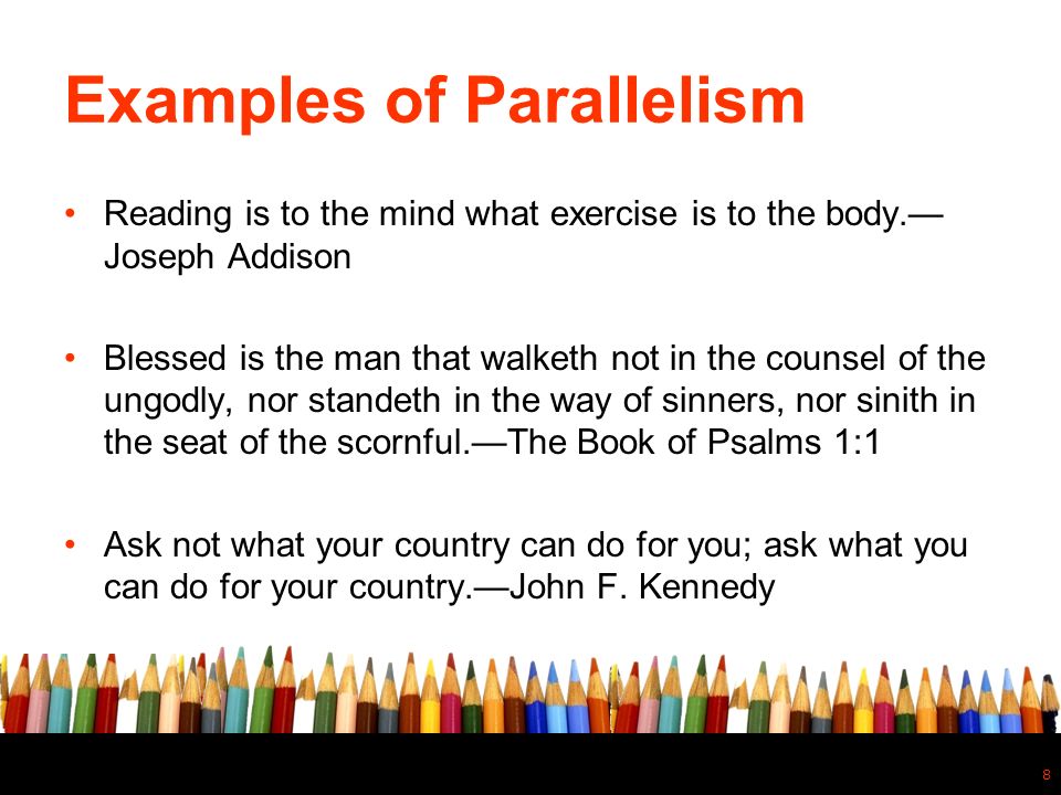
23+ Parallelism Examples PDF Examples

how to draw parallel lines YouTube

How to draw parallel lines? YouTube

How to draw a parallel line through a given point YouTube

Drawing Parallel lines with and without a set square YouTube

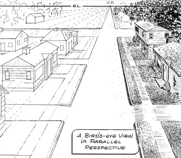
Basics of 1 2 and 3 Point Perspective AKA Parallel and Angular

How To Draw A Line Parallel To A Given Straight Line How to draw a

Draw Parallel Line YouTube

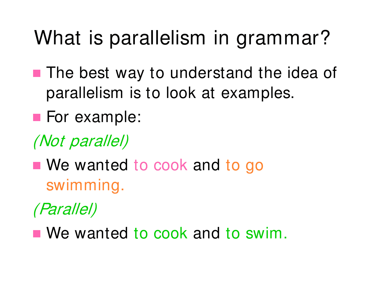
Parallelism In Literature

How to draw a Parallel line at a given distance YouTube
The Distance Between The Parallel Lines, Or Surfaces, Is Specified By The Geometric Tolerance Zone.
Another Way To Call Out These Holes Would Be To Use A Position Tolerance.
The Relevant Feature, Axis, Or Center Plane Must Then Lie Within This Zone.
Currently, We Have 16 Symbols For Geometric Tolerances, Which Are Categorized According To The Tolerance They Specify.
Related Post: