Pid Drawing Symbols
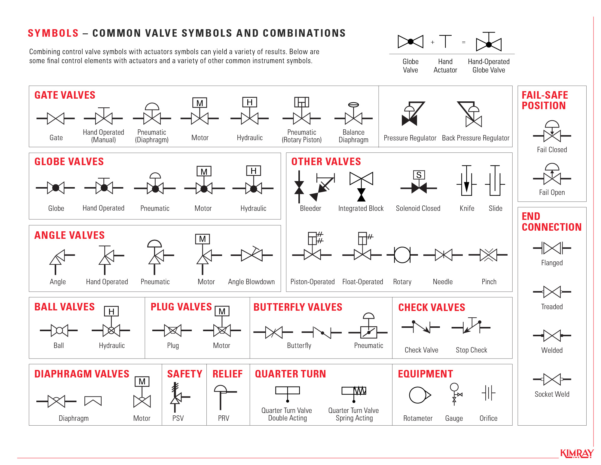
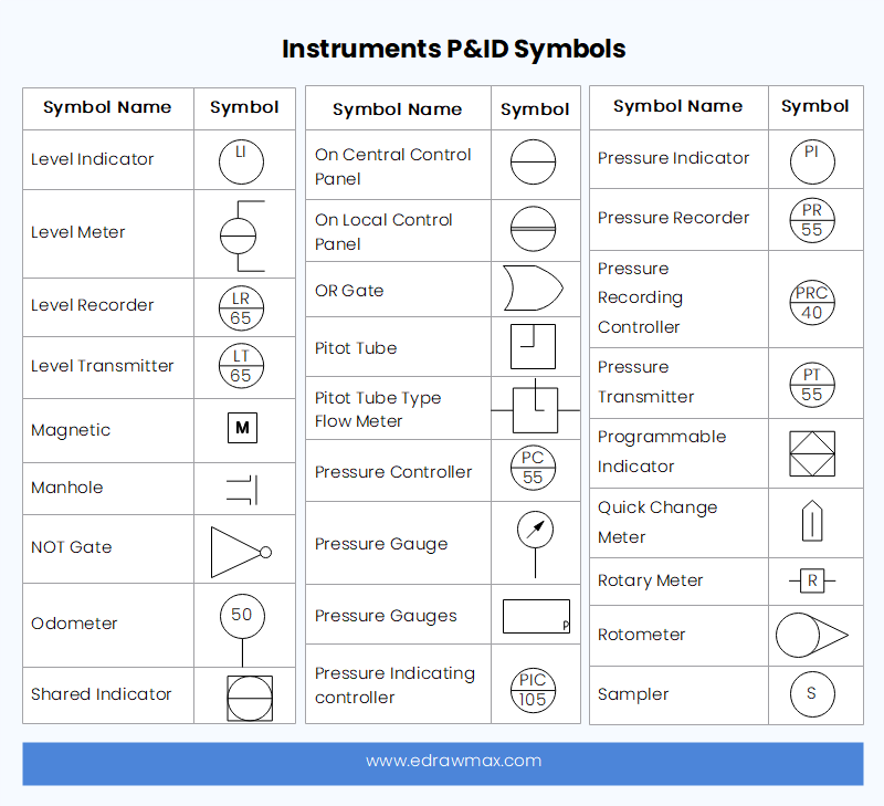
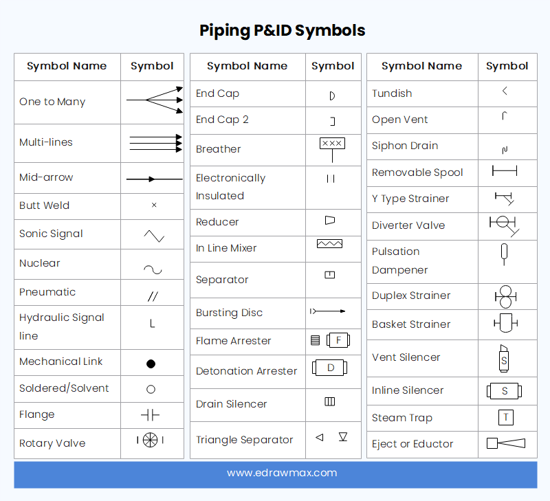
Pid Drawing Symbols - There is an article to introduce p&id symbols. Storage tanks, reactors, columns, drums, etc. Process flow diagram (pfd) or process flow scheme (pfs) piping & instrument diagram (p&id) or process flow engineering scheme (pefs) process & instrument diagram. Web p&ids are a schematic illustration of the functional relationship of piping, instrumentation and system equipment components used in the field of instrumentation and control or automation. Web the common p&id symbols are listed here: An engineer may also include specific details below the. You can choose from abstract symbols and simulation images. It's quick, easy, and completely free. Electric signals are shown as a dotted line, and electromagnetic signals are shown as a wave on a solid line. Solid lines represent pipes, with their size and material indicated by accompanying letters and numbers. Web common p&id symbols include: The p&id is the primary schematic drawing used for laying out a process control system’s installation. Vents, drain, special fittings, sampling lines, reducers, increasers, and other miscellaneous items. It's quick, easy, and completely free. With download pdf for free. Let us look at some of the most famous symbols suitable for smooth functioning across the industry. As this diagram covers many types of diagrams as the variety in industries is vast, many symbols are required. Scroll down or use the table of contents on the left to navigate this page and see the different p&id symbol types commonly used. P&id symbols for piping valves. Web common p&id symbols include: Web piping and instrument diagram standard symbols detailed documentation provides a standard set of shapes & symbols for documenting p&id and pfd, including standard shapes of instrument, valves, pump, heating exchanges, mixers, crushers, vessels, compressors, filters, motors and connecting shapes. The p&id is the primary schematic drawing used for laying. Remember that p&ids represent the hardware and software necessary to design, build, and run a process industry facility. Process piping, sizes, and identification. Web how to draw a piping & instrumentation diagram? An engineer may also include specific details below the. Web piping and instrumentation diagrams (p&ids) use specific instrumentation symbols to show the connectivity of equipment, piping, sensors, and. As said earlier, it is more complex than pfd. Web main process lines are shown as dark black lines, whereas minor lines are shown as thin black lines. An engineer may also include specific details below the. Web some commonly used symbols in p&id diagrams include: This means if some system is shown on a single pfd, it may require. Web piping and instrumentation diagrams (p&ids) use specific symbols to show the connectivity of equipment, sensors, and valves in a control system. Based on the industry and manufacturer, there is a wide variety of symbols. Web what are p&id symbols? Represented by a circle with a triangle pointing towards the center. Web main process lines are shown as dark black. Web engineering drawing abbreviations and symbols are used to communicate and detail the characteristics of an engineering drawing. Mechanical equipment named and listed numerically. Let us look at some of the most famous symbols suitable for smooth functioning across the industry. P&id diagrams are made with specific and standard shapes and symbols. Here you can find what information is contained. In this video, you will learn. This list includes abbreviations common to the vocabulary of people who work with engineering drawings in the manufacture and inspection of parts and assemblies. They are typically created by engineers who are designing a manufacturing process for a physical plant. Process piping, sizes, and identification. Web p&ids will typically include: Your list should include all piping elements, including the order and placement of: Web common p&id symbols include: You can also see the symbols for pneumatic, hydraulic, and capillary lines. Web piping and instrumentation diagrams (p&ids) use specific symbols to show the connectivity of equipment, sensors, and valves in a control system. Web how to draw a piping & instrumentation. Vents, drain, special fittings, sampling lines, reducers, increasers, and other miscellaneous items. As said earlier, it is more complex than pfd. Web a p&id or process and instrumentation diagram provides a detailed graphical representation of the actual process system that includes the piping, equipment, valves, instrumentation, and other process components in the system. You can choose from abstract symbols and. Like all other professional diagrams, p&ids has standard shapes and symbols. Dashed lines often indicate connections to existing systems or future installations. P&id diagrams are made with specific and standard shapes and symbols. Looking for a library of common p&id symbols? Web what are p&id symbols. This means if some system is shown on a single pfd, it may require multiple p&id sheets to show the same system on p&id. P&id is a graphical representation of the actual process plant using various symbols that represent actual equipment. Web a piping and instrumentation diagram (p&id) is a graphic representation of a process system that includes the piping, vessels, control valves, instrumentation, and other process components and equipment in the system. These symbols can represent actuators, sensors, and controllers and may be. Mechanical equipment named and listed numerically. Web a piping and instrumentation diagram (p&id) is defined as follows: Web engineering drawing abbreviations and symbols are used to communicate and detail the characteristics of an engineering drawing. Web how to draw a piping & instrumentation diagram? Web p&ids are a schematic illustration of the functional relationship of piping, instrumentation and system equipment components used in the field of instrumentation and control or automation. In the process industry, a standard set of symbols is. To create such a comprehensive design, start by listing the elements in a standard p&id.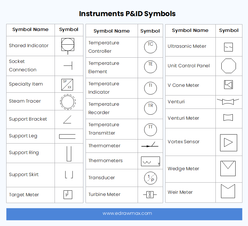
P&ID Symbols and Meanings EdrawMax Online
How to Read Oil and Gas P&ID Symbols Kimray

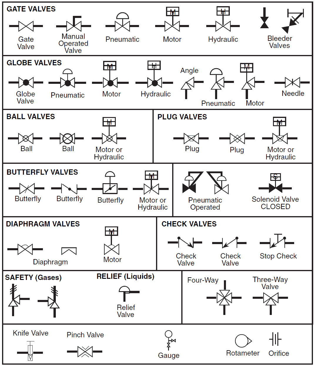
P&ID and PFD Drawing Symbols and Legend list (PFS & PEFS)
P&ID Symbols and Meanings EdrawMax Online

P&ID Symbols & Abbreviations Piping Analysis YouTube

Your Instrumentation Common P&ID Symbols using in industries Tip for

How to Read and Interpret Piping and Instrumentation Diagrams (P&ID
P&ID Symbols and Meanings EdrawMax Online

P&ID Symbols and Notation Lucidchart
P & ID y PFD Drawing Symbols and Legend list (PFS & PEFS) Chad Wilken's
There Is An Article To Introduce P&Id Symbols.
Pumps And Tanks Come In A Variety Of Designs And Shapes.
They Are Typically Created By Engineers Who Are Designing A Manufacturing Process For A Physical Plant.
Process Flow Diagram (Pfd) Or Process Flow Scheme (Pfs) Piping & Instrument Diagram (P&Id) Or Process Flow Engineering Scheme (Pefs) Process & Instrument Diagram.
Related Post: