Piping And Instrumentation Drawing
Piping And Instrumentation Drawing - It serves as a vital tool in the process industry, forming the backbone of the design phase and providing a detailed layout of the plant's process. Standard structures located on a p&id include storage tanks, surge tanks, pumps, heat exchangers, reactors, and distillation columns. Web p&id, or a piping and instrumentation diagram, is a detailed drawing or schematic primarily utilized in the industrial process industry to illustrate the interconnection between piping, equipment and the instrumentation devices used to. Web a piping and instrumentation diagram (p&id) is a comprehensive schematic that illustrates the functional relationship of piping, instrumentation, and system equipment components within a process plant. It is also called as mechanical flow diagram (mfd). These symbols can represent actuators, sensors, and controllers and may be. All components are represented using various p&id symbols. It's a simple way of using lines and symbols to tell the story of how liquids and gases move around, and how machines control them. With a bit of smoke, a few mirrors and a degree in hieroglyphics, anyone can learn to read a p&id. Web a p&id or process and instrumentation diagram provides a detailed graphical representation of the actual process system that includes the piping, equipment, valves, instrumentation, and other process components in the system. Web a p&id or process and instrumentation diagram provides a detailed graphical representation of the actual process system that includes the piping, equipment, valves, instrumentation, and other process components in the system. Web p&id, or a piping and instrumentation diagram, is a detailed drawing or schematic primarily utilized in the industrial process industry to illustrate the interconnection between piping, equipment. Web a piping and instrumentation diagram (p&id) is a comprehensive schematic that illustrates the functional relationship of piping, instrumentation, and system equipment components within a process plant. Web a piping and instrumentation diagram (p&id or pid) is a detailed diagram in the process industry which shows the piping and process equipment together with the instrumentation and control devices. Web a. It is also called as mechanical flow diagram (mfd). The shapes in this legend are representative of the functional relationship between piping, instrumentation, and system equipment units. Web a piping and instrumentation diagram (p&id or pid) is a detailed diagram in the process industry which shows the piping and process equipment together with the instrumentation and control devices. With a. Web piping and instrumentation diagrams (p&ids) use specific symbols to show the connectivity of equipment, sensors, and valves in a control system. It serves as a vital tool in the process industry, forming the backbone of the design phase and providing a detailed layout of the plant's process. Web a p&id or process and instrumentation diagram provides a detailed graphical. Web a piping & instrumentation diagram (p&id) is a schematic layout of a plant that displays the units to be used, the pipes connecting these units, and the sensors and control valves. Web p&id drawing, or piping and instrumentation diagrams, is like a special map that shows how pipes and instruments work together in factories and plants. It’s most commonly. With a bit of smoke, a few mirrors and a degree in hieroglyphics, anyone can learn to read a p&id. Web a piping & instrumentation diagram (p&id) is a schematic layout of a plant that displays the units to be used, the pipes connecting these units, and the sensors and control valves. The shapes in this legend are representative of. It's a simple way of using lines and symbols to tell the story of how liquids and gases move around, and how machines control them. Web piping and instrumentation diagrams, or p&ids, are used to create important documentation for process industry facilities. Web a piping & instrumentation diagram (p&id) is a schematic layout of a plant that displays the units. All components are represented using various p&id symbols. Web a p&id or process and instrumentation diagram provides a detailed graphical representation of the actual process system that includes the piping, equipment, valves, instrumentation, and other process components in the system. It's a simple way of using lines and symbols to tell the story of how liquids and gases move around,. All components are represented using various p&id symbols. Web a piping and instrumentation diagram (p&id or pid) is a detailed diagram in the process industry which shows the piping and process equipment together with the instrumentation and control devices. These symbols can represent actuators, sensors, and controllers and may be. Web a piping and instrumentation diagram (p&id) is a comprehensive. These symbols can represent actuators, sensors, and controllers and may be. All components are represented using various p&id symbols. It’s most commonly used in the engineering field. The shapes in this legend are representative of the functional relationship between piping, instrumentation, and system equipment units. Web a piping and instrumentation diagram (p&id) is a comprehensive schematic that illustrates the functional. Standard structures located on a p&id include storage tanks, surge tanks, pumps, heat exchangers, reactors, and distillation columns. Web a piping and instrumentation diagram (p&id or pid) is a detailed diagram in the process industry which shows the piping and process equipment together with the instrumentation and control devices. Web piping and instrumentation diagrams (p&ids) use specific symbols to show the connectivity of equipment, sensors, and valves in a control system. Web a piping and instrumentation diagram (p&id) is a comprehensive schematic that illustrates the functional relationship of piping, instrumentation, and system equipment components within a process plant. Web p&id, or a piping and instrumentation diagram, is a detailed drawing or schematic primarily utilized in the industrial process industry to illustrate the interconnection between piping, equipment and the instrumentation devices used to. It is also called as mechanical flow diagram (mfd). Web p&id drawing, or piping and instrumentation diagrams, is like a special map that shows how pipes and instruments work together in factories and plants. By chenected guest on aug 24, 2010. All components are represented using various p&id symbols. How to interpret piping and instrumentation diagrams. It serves as a vital tool in the process industry, forming the backbone of the design phase and providing a detailed layout of the plant's process. These symbols can represent actuators, sensors, and controllers and may be. The shapes in this legend are representative of the functional relationship between piping, instrumentation, and system equipment units. With a bit of smoke, a few mirrors and a degree in hieroglyphics, anyone can learn to read a p&id. Web a piping & instrumentation diagram (p&id) is a schematic layout of a plant that displays the units to be used, the pipes connecting these units, and the sensors and control valves. It's a simple way of using lines and symbols to tell the story of how liquids and gases move around, and how machines control them.
How to Read and Interpret Piping and Instrumentation Diagrams (P&ID
Figure A4 Piping and Instrumentation Diagram 1 Download Scientific
Piping And Instrumentation Diagram Piping and Instrumentation

Piping & Instrumentation Diagrams (P&IDs) Punchlist Zero
Piping and Instrumentation Diagram P&ID By TheEngineeringConcepts
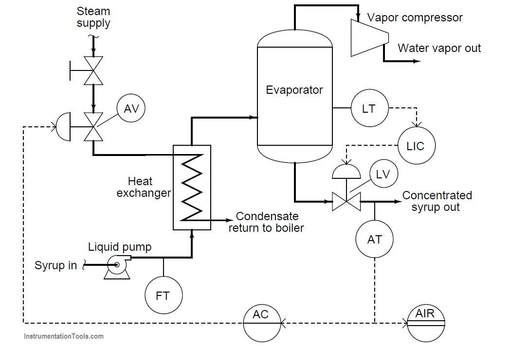
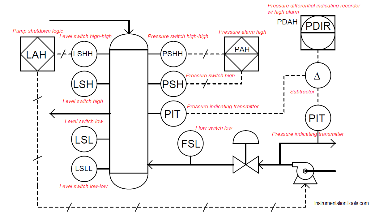
What is Piping and Instrumentation Diagram (P&ID) ? Instrumentation Tools
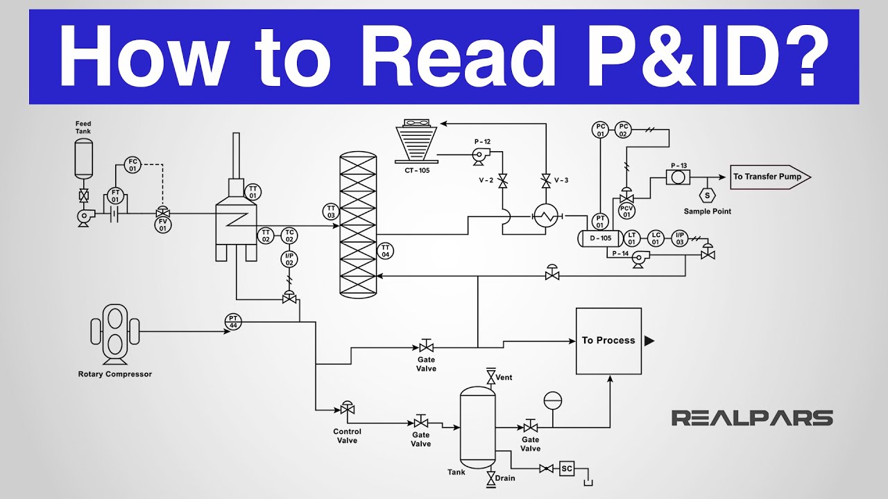
How to Read a P&ID? (Piping & Instrumentation Diagram) YouTube
Piping and Instrumentation Documents Instrumentation Tools
Identify Instruments in Piping and instrumentation Diagram
Solved Consider the Piping and Instrumentation Diagram
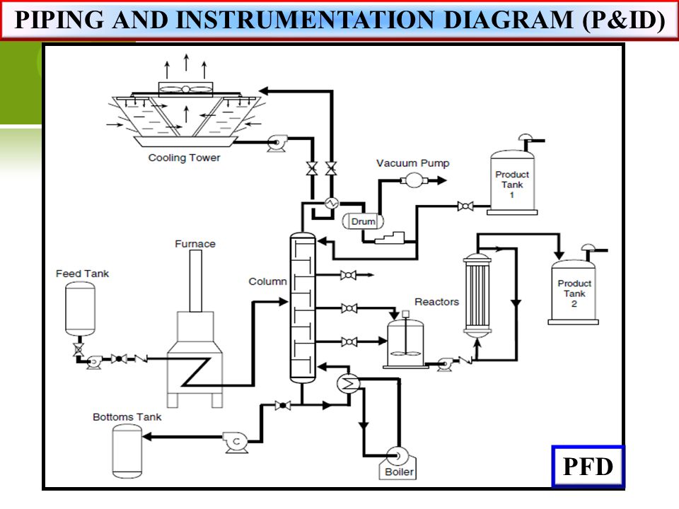
Web A Piping And Instrumentation Diagram, Or P&Id, Shows The Piping And Related Components Of A Physical Process Flow.
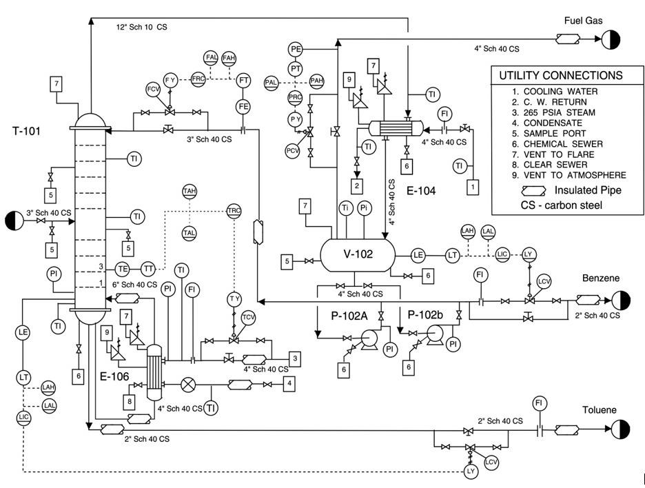
Web A P&Id Or Process And Instrumentation Diagram Provides A Detailed Graphical Representation Of The Actual Process System That Includes The Piping, Equipment, Valves, Instrumentation, And Other Process Components In The System.
It’s Most Commonly Used In The Engineering Field.
Web Piping And Instrumentation Diagrams, Or P&Ids, Are Used To Create Important Documentation For Process Industry Facilities.
Related Post: