Terminal Block Symbol In Electrical Drawing
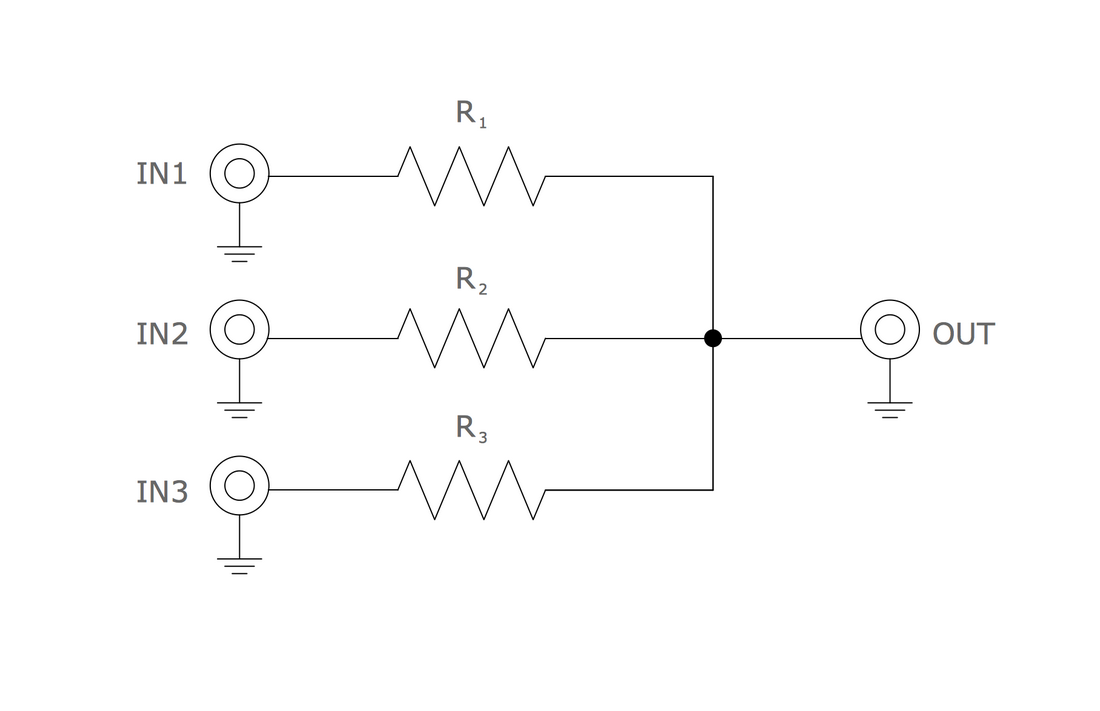
Terminal Block Symbol In Electrical Drawing - Common symbols for basic components. They make wiring modifications extremely easy as they allow for wires to be connected/disconnected easily. So if we follow dc over, [3m:48s] and in this case there's still double block. Inserting terminal symbols into drawings. Select the terminal to edit. These are in addition to the standard attributes such as mfg, cat, p_tagstrip, etc. Each terminal on the block is assigned a unique number or label, which helps to identify and reference the specific connection points. Schematic central enhance your electronics knowledge Web terminal symbols on the schematic are a representation of wire connection points. Each level carries certain characteristics, such as a label, wires per connection, left pin, and right pin. The “##” represents a two character level number (ie: Vt1001 (it's a terminal with wirenumber change) and copy the attributes to your symbol and save. The terminal is represented by a square with sides of 4 mm. Common symbols for basic components. Inserting terminal symbols into drawings. Switches make or break a connection in a circuit. The terminal symbol representation on the schematic can have associations with the physical terminal block on the panel drawing. In my experience, and what is the format in several cad packages i have used is something similar to the following, for the schematic view you have the following: Web overall, the. Web a terminal block diagram is a visual representation of the connections and components of a terminal block. These schematics use standardized symbols and labels to represent different electrical components and their connections. Svg png jpg dxf dwg. Each terminal on the block is assigned a unique number or label, which helps to identify and reference the specific connection points.. The “##” represents a two character level number (ie: The terminals are typically labeled with letters or numbers. Web some of the most common symbols include: Web learn about terminal block wiring and how to properly connect and secure wires in electrical systems using terminal blocks. These are in addition to the standard attributes such as mfg, cat, p_tagstrip, etc. This is represented as a fused terminal block. They also let you change the path of current flow. Web terminal blocks are used in electrical panels and systems to quickly and safely allow for the connection of wires to certain points of a circuit. Web some of the most common symbols include: Common symbols for basic components. Select the terminal to edit. Web overall, the terminal block schematic symbol provides a visual representation of the physical components and connections of the terminal block. Web terminal blocks are used in electrical panels and systems to quickly and safely allow for the connection of wires to certain points of a circuit. Each level carries certain characteristics, such as a. A spst (single pole, single throw) switch is an on and off switch. Web terminal block symbols: Web welcome to this instructional video on how to draw terminal blocks in proficad. You can open for example the symbol: Web overall, the terminal block schematic symbol provides a visual representation of the physical components and connections of the terminal block. They make wiring modifications extremely easy as they allow for wires to be connected/disconnected easily. The other elements, like texts, attributes, and graphical representation of cables are drawn according to the configuration parameters. Select the terminal to edit. Web terminal blocks are used in electrical panels and systems to quickly and safely allow for the connection of wires to certain. The symbols represent electrical and electronic components. Web a terminal block diagram is a visual representation of the connections and components of a terminal block. The terminal is represented by a square with sides of 4 mm. A spst (single pole, single throw) switch is an on and off switch. The terminals are typically labeled with letters or numbers. Web terminal connections are different from nodes or junctions which have solid circles: The terminals are typically labeled with letters or numbers. Each level carries certain characteristics, such as a label, wires per connection, left pin, and right pin. These are in addition to the standard attributes such as mfg, cat, p_tagstrip, etc. You can open for example the symbol: They make wiring modifications extremely easy as they allow for wires to be connected/disconnected easily. You may already have the terminal symbol in your library, but just to be sure, we'll show you how to draw it. The symbols represent electrical and electronic components. The number of levels for the terminal is defined as a block property. So, this is a regular terminal block, this is a fuse terminal block. Select additional terminal symbols to add to the association of the master terminal. Web terminal connections are different from nodes or junctions which have solid circles: Web you can use the default symbols (most of the terminals have the same representation) or use symbols associated with the manufacturer parts or scheme symbols (each terminal can have this own representation). The direction of the current is indicated by an arrow. These controls determine the overall tagging of the terminal block in the project. This is represented as a fused terminal block. Web you can modify the symbol to a autocad electrical symbol with the black box builder and define it as a terminal. Web terminal symbols on the schematic are a representation of wire connection points. You can open for example the symbol: These are in addition to the standard attributes such as mfg, cat, p_tagstrip, etc. Wires are represented by a simple line with a dot at each end.
Terminal Block Wiring Diagram A Complete Guide Moo Wiring
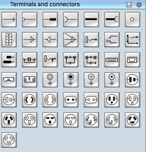
Electrical Symbols Terminals and Connectors

Electrical Schematic Symbol Connectors CAD Block And Typical
Wiring Diagrams For Terminal Blocks
Electrical Symbols Electrical Schematic Symbols

Symbols Used In Electrical Schematic Drawing

Electrical Panel Wiring Diagram Symbols Diagram Circuit

TERMINAL CAD Block And Typical Drawing
Schematic Terminals AutoCAD Electrical 2022 Autodesk Knowledge Network

Terminal Block Electrical Wiring Diagram Control Complete Wiring Schemas
Web Some Of The Most Common Symbols Include:
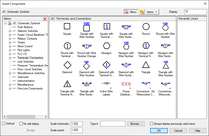
Select Terminals And Connectors, Select The Terminal To Insert, And Specify The Insertion Point On The Drawing.
Inserting Terminal Symbols Into Drawings.
These Schematics Use Standardized Symbols And Labels To Represent Different Electrical Components And Their Connections.
Related Post: