Volt Ohm Meter Drawing
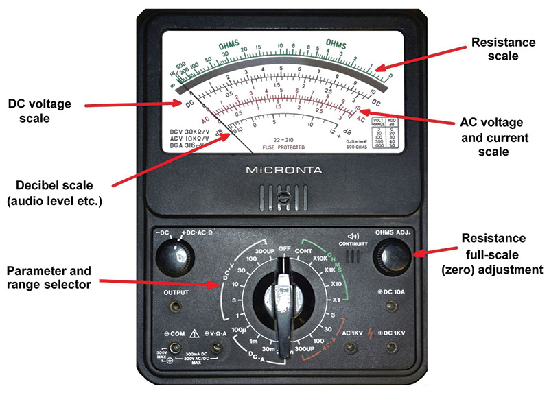
Volt Ohm Meter Drawing - Web schematic of volt / ammeter. The normal practice is to provide several ranges for each function. Web the ohmmeter applies a voltage to the circuit or component and it measures the magnitude of electric current flowing through the component. Note the many scales on the face of the meter movement for the different ranges and functions selectable by the rotary switch. The multimeter is used for. This particular voltmeter has several different voltage measurement ranges to choose from: Direct current (dc) chapter 8 dc metering circuits. As was stated earlier, most meter movements are sensitive devices. E = (1 ma) (500 ω) e = 0.5 volts. Web simple attach the test leads to the dut (device under test) and read the voltage/current/resistance from the screen. Web learn how to measure voltage and current in electrical circuits using voltmeters and ammeters. Note the many scales on the face of the meter movement for the different ranges and functions selectable by the rotary switch. Understand the importance of resistance in these devices to ensure accurate readings and prevent damage. The various multimeter symbols include: Web a digital. Initially, follow the instructions below to build the multimeter circuit on a breadboard first while determining proper range resistance values and performing all calibration adjustments there. E = (1 ma) (500 ω) e = 0.5 volts. Discover why voltmeters are connected in parallel and ammeters in series. Web learn how to measure voltage and current in electrical circuits using voltmeters. If all we wanted was a meter that could measure 1/2 of a volt, the bare meter movement we have here would suffice. The internal circuitry of the ohmmeter then calculates the resistance using ohms’s law by dividing voltage by current. As was stated earlier, most meter movements are sensitive devices. Understand the importance of resistance in these devices to. Most ohmmeters of the design shown in the previous section utilize a battery of relatively low voltage, usually nine volts or less. As was stated earlier, most meter movements are sensitive devices. Direct current (dc) chapter 8 dc metering circuits. Depending on your multimeter, you may have two different voltage ranges to choose from, 200v~ and 600v~, and it may. Direct current (dc) chapter 8 dc metering circuits. Web types of voms, sources, wiring diagrams, repair advice. A typical multimeter can measure voltage, resistance, and current, in which case can be used as a voltmeter, ohmmeter, and ammeter. In other words, in vom the multiple measuring functions are combined in a single unit. Note the many scales on the face. The following is an explanation of the most common multimeter symbols. Understand the importance of resistance in these devices to ensure accurate readings and prevent damage. Though mechanical ohmmeter (resistance meter) designs are rarely used today, having largely been superseded by digital instruments, their operation is nonetheless intriguing and worthy of study. Web types of voms, sources, wiring diagrams, repair. This particular voltmeter has several different voltage measurement ranges to choose from: A vom is a voltmeter, ammeter, and ohmmeter, all in one. Web ac voltage is typically measured in volts (v) and is represented by the symbol “ṽ” on your multimeter. E = (1 ma) (500 ω) e = 0.5 volts. When measuring voltage, for example, the multimeter detects. Web voltmeter design and use. Thus, the ratio of voltage to current is the resistance of the component or circuit. The vom has the advantages of being inexpensive and portable. Web schematic of volt / ammeter. Initially, follow the instructions below to build the multimeter circuit on a breadboard first while determining proper range resistance values and performing all calibration. Thus, the ratio of voltage to current is the resistance of the component or circuit. Web voltmeter design and use. Web ac voltage is typically measured in volts (v) and is represented by the symbol “ṽ” on your multimeter. Web a digital multimeter works by measuring the electrical properties of a circuit and converting these measurements into a digital readout.. If all we wanted was a meter that could measure 1/2 of a volt, the bare meter movement we have here would suffice. Web a digital multimeter works by measuring the electrical properties of a circuit and converting these measurements into a digital readout. The vom has the advantages of being inexpensive and portable. The following is an explanation of. The internal circuitry of the ohmmeter then calculates the resistance using ohms’s law by dividing voltage by current. A typical multimeter can measure voltage, resistance, and current, in which case can be used as a voltmeter, ohmmeter, and ammeter. Circuit diagram of a series type ohmmeter. As was stated earlier, most meter movements are sensitive devices. Web chapter 8 dc metering circuits. Web simple attach the test leads to the dut (device under test) and read the voltage/current/resistance from the screen. If all we wanted was a meter that could measure 1/2 of a volt, the bare meter movement we have here would suffice. Web check out this ohmmeter built and coded from scratch using an arduino, 8 precision resistors, a multiplexer, and an oled display! Most ohmmeters of the design shown in the previous section utilize a battery of relatively low voltage, usually nine volts or less. The multimeter is used for. A vom is a voltmeter, ammeter, and ohmmeter, all in one. This setting commonly measures voltages between 100 and 240 ac volts in homes and offices. Though mechanical ohmmeter (resistance meter) designs are rarely used today, having largely been superseded by digital instruments, their operation is nonetheless intriguing and worthy of study. Thus, the ratio of voltage to current is the resistance of the component or circuit. The unit shown above is typical of a handheld analog multimeter, with ranges for voltage, current, and resistance measurement. Initially, follow the instructions below to build the multimeter circuit on a breadboard first while determining proper range resistance values and performing all calibration adjustments there.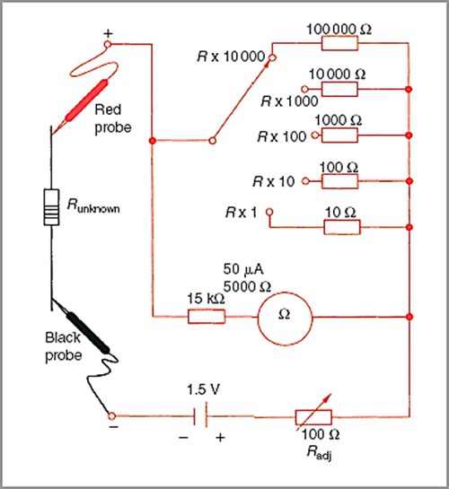
Ohm Meter Circuit Diagram

Voltmeter Royalty Free Vector Image VectorStock

Intro Lab How to Use a Voltmeter to Measure Voltage Basic Projects

How to Use a Volt ohm Multimeter Missouri Wind and Solar YouTube
How to use a multimeter or voltmeter Basics you need to know. YouTube

How to Correctly use a Volt/Ohm Meter or Multimeter AV TechTips YouTube
What is VoltOhmMilliAmmeter (VOM)? Definition & Explanation
![]()
Digital Multimeter for Measuring Electrical Indicators AC DC Voltage

Analog Multimeter VoltOhmMillimeter CE Distribution
The Care and Feeding of Analog Meters Nuts & Volts Magazine
Discover Why Voltmeters Are Connected In Parallel And Ammeters In Series.
Understand The Importance Of Resistance In These Devices To Ensure Accurate Readings And Prevent Damage.
Web The Ohmmeter Applies A Voltage To The Circuit Or Component And It Measures The Magnitude Of Electric Current Flowing Through The Component.
Web Ac Voltage Is Typically Measured In Volts (V) And Is Represented By The Symbol “Ṽ” On Your Multimeter.
Related Post: