Weld Symbol On Drawings
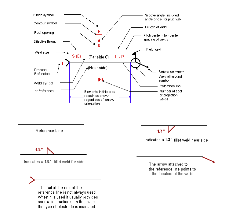
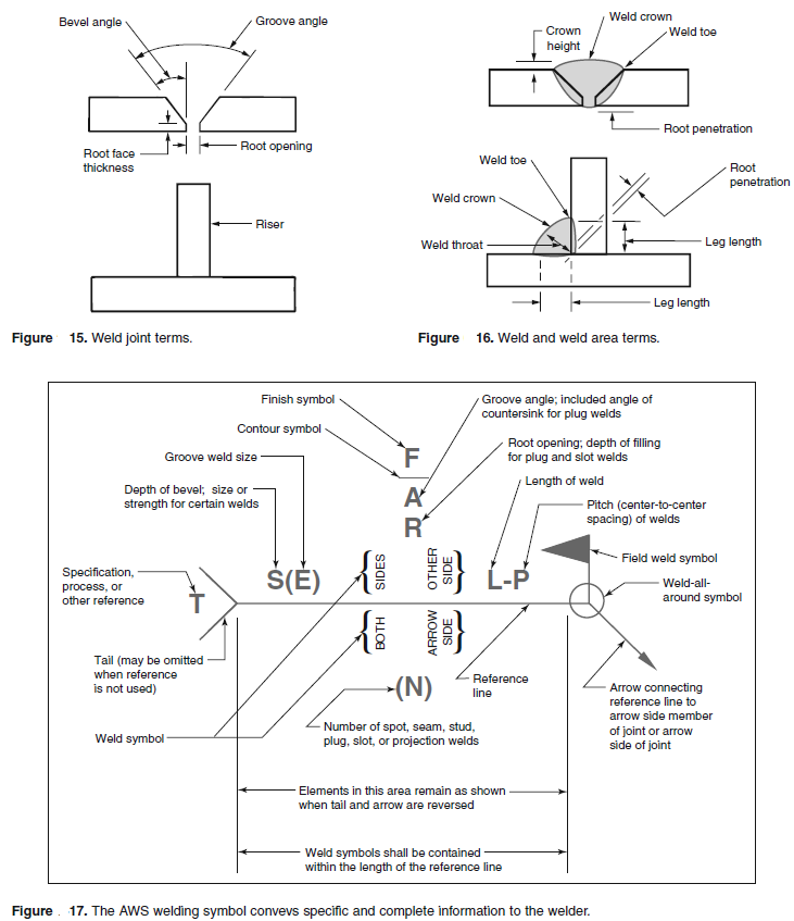
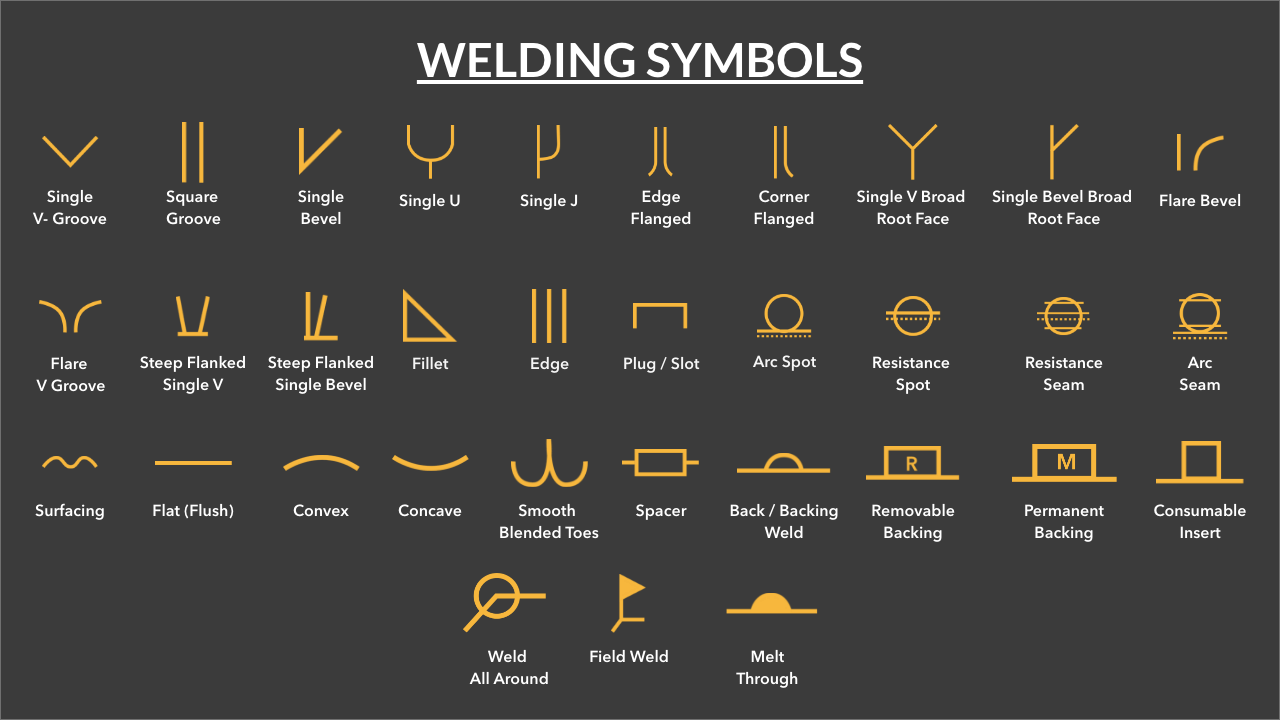
Weld Symbol On Drawings - A symbol can be used to specify the weld type, groove design, welding process, face & root contour,. Older drawings may denote a field weld by a filled black circle at the junction between the arrow and reference line. Resistance seam weld with no side significance, 8” pitch, 16” length. These symbols are usually found in fabrication and engineering drawings. Base system b here, when the welding symbol is on the underside of the reference line, the weld is. These sit on the arrow or the other side of the reference line, indicating the type of weld.; Web a welding symbol can be a pretty complex drawing that consists of basic weld symbols and supplementary symbols, numbers, and letters that can define every single aspect of a specified weld. Basic weld symbol the weld symbol always includes 1. A weld symbol would differentiate between two sides of a joint using arrows and the spaces on top and under the reference line. It is essential that the 'rules' of the standard used are correctly applied by drawing office personnel. They allow precise communication of the. A welding symbol uses ‘ weld symbols ‘ to. It communicates the location of welding, the type of welding, and all the other details required by the fabricator to execute the fabrication. A., welding symbols on drawings, abington, cambridge: Web ask the assistant. Users reported that in inventor drawing, moving text notes with symbol annotation (like sketch symbols or surface symbols) is inconsistent. Web the weld symbol always includes. However, each element of the welding symbol has its specified location. Web the weld symbols are always placed on the reference line of the welding symbol. The open circle at the arrow/reference line junction. A welding symbol uses ‘ weld symbols ‘ to. Web symbols (3.8) and supplementary symbols (3.9), dimensions and/or tail, used on technical drawings note 1 to entry: The reference line is a horizontal line that is used to align the other elements of the symbol. 1” stud welds on the arrow side, 2” pitch, 20 total studs. It is essential. A welding symbol is what you see on the fabrication drawing. Complete weld representation methods consist of the basic symbol, auxiliary symbol, supplementary symbol, leader, dimension symbol, and data. Resistance seam weld with no side significance, 8” pitch, 16” length. 1/4” stud welds on the arrow side with a. However, it is also important that shop floor personnel are able. Web the weld symbol always includes. 3.2 basic welding symbol symbol consisting of an arrow line (3.3), reference line (3.4) and tail used when the joint is not specified and only to indicate that a welded joint is to be made note 1 to entry: Web drawing page drawing of weld symbols standards the british standard for weld symbols is. Web position of welding symbols on drawings 1. Web the weld symbols are always placed on the reference line of the welding symbol. They allow precise communication of the. Web welding symbols are a graphical way to convey information about a welding joint. Create a weld bead component in an assembly. Base system b here, when the welding symbol is on the underside of the reference line, the weld is. The arrow may point up or down. Weld symbols on the full reference line relates to welds on the near side of the plate being welded. The leader line is composed of an arrow leader line (also known as an arrow. When identification of the weld process is required as part of the weld symbol the relevant weld process code is listed in bs en iso 4063. Web the weld symbol always includes. Web the weld symbol always includes. They allow precise communication of the. It is essential that the 'rules' of the standard used are correctly applied by drawing office. This is where the symbols sit.; Web a weld symbol without a flag indicates that the weld is to be made in the shop. There are three main elements to a weld symbol: Therefore, you can get a weld symbol that seems messy and needs clarification. Web the weld symbol always includes. Web position of welding symbols on drawings 1. However, each element of the welding symbol has its specified location. This is just barely skimming the surface of weld symbols training. Older drawings may denote a field weld by a filled black circle at the junction between the arrow and reference line. Instead of using an arrow and saying ‘weld here’,. Web the weld symbol always includes. Resistance seam weld with no side significance, 8” pitch, 16” length. It communicates the location of welding, the type of welding, and all the other details required by the fabricator to execute the fabrication. Web drawing page drawing of weld symbols standards the british standard for weld symbols is bs en 22553. However, each element of the welding symbol has its specified location. Older drawings may denote a field weld by a filled black circle at the junction between the arrow and reference line. When identification of the weld process is required as part of the weld symbol the relevant weld process code is listed in bs en iso 4063. However, it is also important that shop floor personnel are able to read and understand the details of weld symbols. Base system b here, when the welding symbol is on the underside of the reference line, the weld is. Therefore, you can get a weld symbol that seems messy and needs clarification. It is essential that the 'rules' of the standard used are correctly applied by drawing office personnel. Web symbols (3.8) and supplementary symbols (3.9), dimensions and/or tail, used on technical drawings note 1 to entry: Web the 9 steps below represent a very basic introduction to welding symbols. There are three main elements to a weld symbol: Web the weld symbol always includes. Weld symbols on the dashed line relates to weld on the far side of the plate.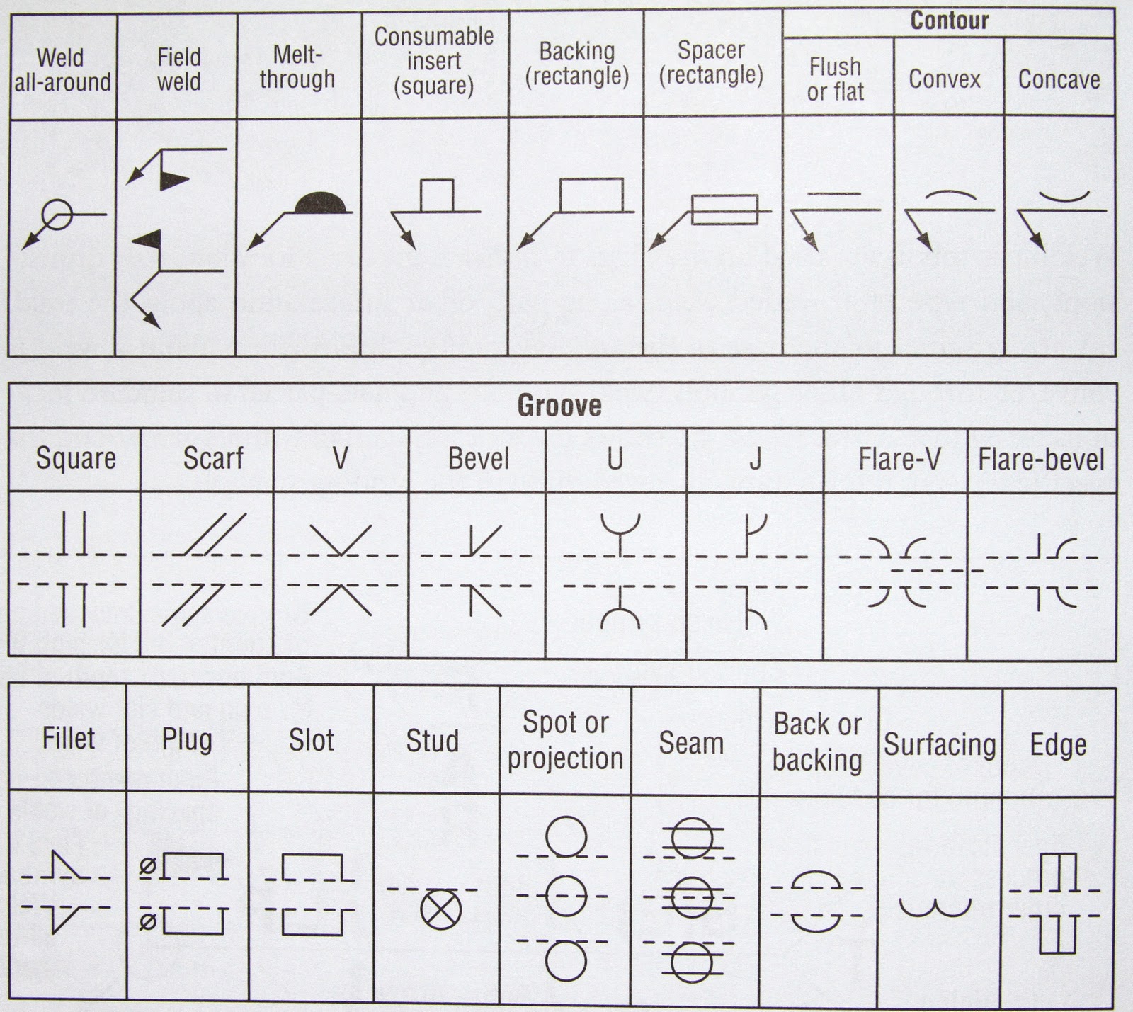
Basic Welding Symbols Weld My World
Weld Symbols Chart American Welding Society DWG file Autodesk_AutoCAD
Understanding the Welding Symbols in Engineering Drawings Safe Work

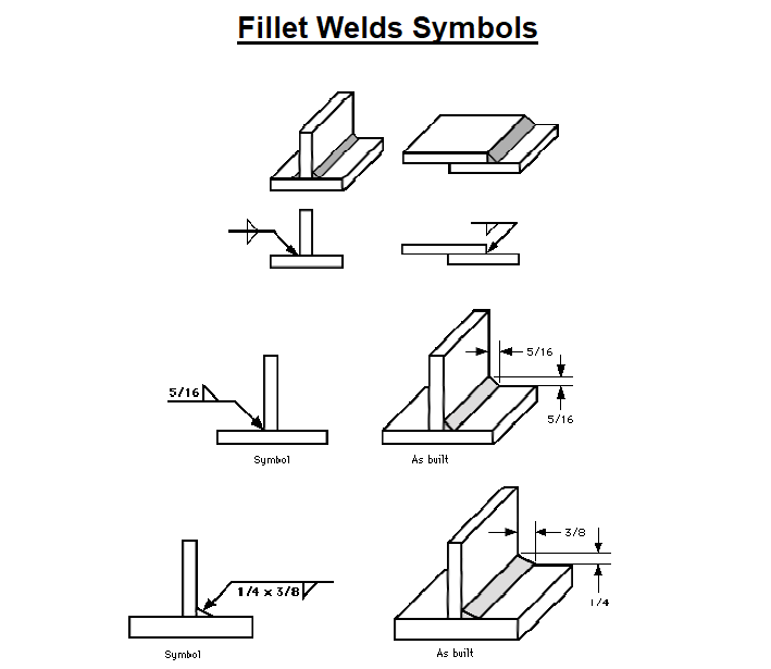
Weld Symbols
Understanding the Welding Symbols in Engineering Drawings Safe Work
Welding Terms and Symbols Basic welding symbols Engineersfield

Welding Symbols with Figures PAKTECHPOINT

Understanding the Basic Welding Symbols

Welding Symbols Guide And Chart Fillet and Groove Weld
How to Read Welding Blueprints Like a Pro
Since The Symbols Are Standardized, They Provide Consistency Across Different Drawings, Irrespective Of Who The Designer Or The Welder Is.
They Allow Precise Communication Of The.
Web The Weld Symbols Are Always Placed On The Reference Line Of The Welding Symbol.
Weld Symbols Are A Very Useful Way Of Communicating Welding Requirements From The Design Office To The Shop Floor.
Related Post: