What Is Schematic Drawing
What Is Schematic Drawing - It uses standardized symbols to represent electronic components and shows how these components are connected to form a circuit. These will usually be drawn in a line format from left to right, but are not analogous to ladder diagrams. Although schematic diagrams are commonly associated with electrical circuits, many examples can be found in other industries. After seeing a few circuit diagrams, you’ll quickly learn how to distinguish the different symbols. It shows the electrical components and interconnections of the circuit using standardized symbols and lines. They’re like a map for building or troubleshooting circuits, and can tell you almost everything you need to know to understand how a circuit works. We'll go over all of the fundamental schematic symbols: In this work, we present independent determinations of cosmological parameters and new constraints on f(t) cosmologies, employing two new catalogs related to hii galaxy hubble and cmb. Web an electrical schematic is a diagram that shows how all of the wires and components in an electronic circuit are connected. Web an electrical schematic, also known as a wiring diagram or circuit diagram, is a visual representation of an electrical circuit. Shows how components are related to others on the same circuit, but contains less detailed information about electrical connections. Some diagrams may have realistic pictures to make the various components easier to identify. The ability to read electrical schematics is a really useful skill to have. Web a class diagram is a uml diagram type that describes a system by. Web schematics are our map to designing, building, and troubleshooting circuits. Web the schematic diagram, also referred to as a circuit diagram, serves as the blueprint for any electrical circuit, laying out the components and connections that bring a circuit from concept to reality. We'll go over all of the fundamental schematic symbols: The ability to read electrical schematics is. It shows the electrical components and interconnections of the circuit using standardized symbols and lines. Web a schematic diagram is a picture that represents the components of a process, device, or other object using abstract, often standardized symbols and lines. We'll go over all of the fundamental schematic symbols: Schematics have two fundamental purposes. As such, its purpose is to. Web an electrical schematic, also known as a wiring diagram or circuit diagram, is a visual representation of an electrical circuit. We'll go over all of the fundamental schematic symbols: It is a way to illustrate complex ideas or concepts in a. This stage involves creating rough sketches and drawings to explore and illustrate the basic size, layout, and relationships. Wiring diagrams show specific electrical connections. Web a circuit diagram, or a schematic diagram, is a technical drawing of how to connect electronic components to get a certain function. It is vital for a pcb designer to get familiarized with the schematic symbols that represent the components on a schematic diagram. Web there are three basic types of wiring diagrams:. Web an electrical schematic is a diagram that shows how all of the wires and components in an electronic circuit are connected. Schematic design occupies either the first or the second place in the usual five phases of creating a design for your. Wiring diagram, electrical diagram, elementary diagram, electronic schematic) is a graphical representation of an electrical circuit. Web. Wiring diagrams show specific electrical connections. Web schematic design is a phase in the architectural design process where architects and designers develop initial concepts and layouts for a project. Web the schematic diagram, also referred to as a circuit diagram, serves as the blueprint for any electrical circuit, laying out the components and connections that bring a circuit from concept. This tutorial should turn you into a fully literate schematic reader! Web a circuit diagram, or a schematic diagram, is a technical drawing of how to connect electronic components to get a certain function. Web circuit schematics are the bridge between conceptual electrical design and physical realization of a printed circuit board assembly, or pcba. Web cosmologies with hii hubble. Web basic electrical and electronic graphical symbols called schematic symbols are commonly used within circuit diagrams, schematics and computer aided drawing packages to identify the position of individual components and elements within a circuit. These will usually be drawn in a line format from left to right, but are not analogous to ladder diagrams. Web a pictorial diagram uses pictures. Web an electrical schematic, also known as a wiring diagram or circuit diagram, is a visual representation of an electrical circuit. What comes after the schematic design phase? Web a circuit diagram, or a schematic diagram, is a technical drawing of how to connect electronic components to get a certain function. Understanding how to read and follow schematics is an. They are usually used to explore domain concepts, understand software requirements and. Understanding how to read and follow schematics is an important skill for any electronics engineer. 10 simple steps to learn electronics. Web a schematic, or schematic diagram, is a designed representation of the elements of a system using abstract, graphic symbols rather than realistic pictures. Web a circuit diagram, or a schematic diagram, is a technical drawing of how to connect electronic components to get a certain function. Web schematic design is a phase in the architectural design process where architects and designers develop initial concepts and layouts for a project. Schematic design occupies either the first or the second place in the usual five phases of creating a design for your. Unlike a pictorial diagram, a schematic doesn’t aim to represent the physical layout of the components. Web the idea of the electrical or wiring diagram is to trace the flow of power and signals between the sources, control devices, and final loads. Depicts electrical devices as drawings or pictures connected by lines representing wires. Some diagrams may have realistic pictures to make the various components easier to identify. It is a way to illustrate complex ideas or concepts in a. Web basic electrical and electronic graphical symbols called schematic symbols are commonly used within circuit diagrams, schematics and computer aided drawing packages to identify the position of individual components and elements within a circuit. These will usually be drawn in a line format from left to right, but are not analogous to ladder diagrams. Web schematics are our map to designing, building, and troubleshooting circuits. In this work, we present independent determinations of cosmological parameters and new constraints on f(t) cosmologies, employing two new catalogs related to hii galaxy hubble and cmb.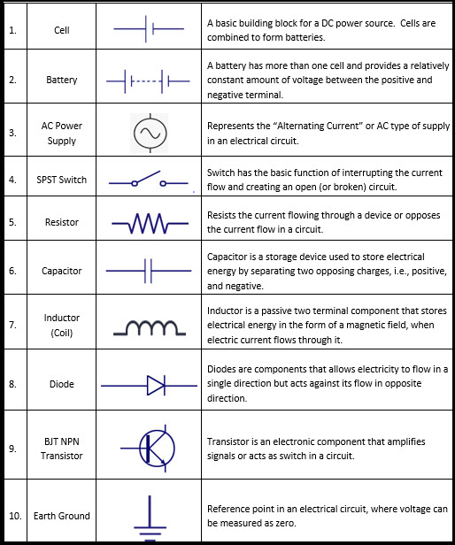
Important schematic symbols for designing circuits GBC Electronics
What Is the Meaning of Schematic Diagram? Sierra Circuits
Schematic Drawing at Explore collection of

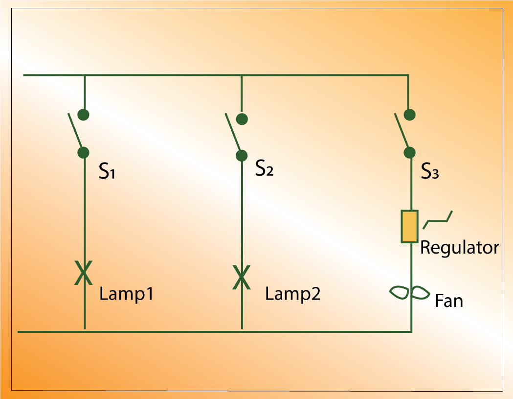
Basic Schematic Diagram Example Wiring Technology
How to Draw Electrical Schematics Edraw

A drawing showing all significant components,parts, or tasks (and their

How to Read a Schematic SparkFun Learn
How To Draw Schematics keep going and going and wiring

What is a Schematic Diagram? Electrical and PLC Tutorials YouTube
Schematic Diagram Maker Free Online App
What Comes After The Schematic Design Phase?
First, They Communicate Design Intent.
Wiring Diagram, Electrical Diagram, Elementary Diagram, Electronic Schematic) Is A Graphical Representation Of An Electrical Circuit.
A Shows Connections In A Circuit In A Way That Is Clear And Standardized.
Related Post: